Crossrail Gets Its Rails
There is an article in Rail Engineer with this title and it describes how Crossrail’s contractors will fit out the line.
In some ways, one thing that surprised me is that the massive concreting train, that lays the concrete slab for the rails is a refurbished one from France. At least they were able to drag it here, through the Channel Tunnel.
It’s a fascinating article, that is well worth reading.
Signs Of The Northern Line Extension
I have been past Battersea Power Station twice in the last few days and have been able to take pictures of the conveyors linking the excavations of the now-started Northern Line Extension to the river.
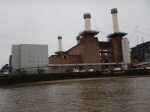
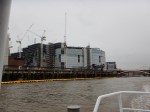
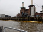
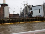
I do wish I could find a train from which it is possible to get a decent photograph of the conveyors and the barge, which is used to take the spoil away. Sadly, it wasn’t there when I took the Thames Clipper trip yesterday.
In this article in the Railway Gazette, the following is said.
Boring of twin tunnels is due to begin in early 2017 and is expected to take six months to complete. An expected 680 000 tonnes of material would be excavated. A 300 m long conveyor belt will carry 92% of this to the River Thames, from where barges will carry it to Goshems Farm in East Tilbury to the east of London.
This is only a small project compared to Crossrail or Crossrail 2, but you have to wonder, if we should be doing a few smaller rail projects like this, to squeeze more capacity out of our overcrowded railways, metros and trams.
In London some smaller projects come to mind.
- Extending the Victoria Line to Herne Hill station, which I wrote about in Could The Victoria Line Go To Herne Hill?
- Extending the Bakerloo Line, which according to this TfL press release has overwhelming support.
- Reinstating the Hall Farm Curve to allow direct services between the Chingford Branch Line and Stratford.
- Connecting the Central and East London Lines at Shoreditch High Street station.
The only certainty, is that the projects that get started will surprise us.
Crossrail 2 October 2015 – Tunnels, Shafts And Head-Houses
Crossrail 2’s underground structures will be very similar to those of Crossrail.
Tunnels
The tunnels will be built in the same way to those of Crossrail, using tunnel boring machines or TBMs.
But I believe there will be slight differences.
- The tunnels of High Speed One, which Crossrail 2 has to cross at Dalston, are at a depth of 34 to 50 metres, so will we see Crossrail 2 bored across London below all the other foundations and infrastructure?
- Crossrail 2 will be built some years after Crossrail and tunnelling technology is improving by leaps and bounds.
- Because Crossrail 2 tunnels will be going through similar terrain to Crossrail, I wouldn’t be surprised to see a much faster process, simply because everything is easier, the second time around.
- Tunnel spoil will probably be taken away by rail, as only the Tottenham Hale site has access to water.
These tunnels under London are getting very much a routine task.
Shafts
There is a Crossrail 2 document entitled Crossrail 2 Shafts.
This is said about the need for shafts.
Shafts would connect the underground Crossrail 2 tunnels with the surface. During everyday operations, the motion of trains would push air out of the tunnels and pull air into them from the atmosphere. As the air pushed out is usually warmer than the air pulled in, the shafts would help to provide a more comfortable temperature for passengers and staff. During periods of disturbed service, when trains could be held in Crossrail 2’s tunnels for an extended period of time, the shaft’s ventilation system would deliver cooler air from the atmosphere to the tunnels and to stationary trains. In the unlikely event of a fire, the shafts would control smoke, provide access for the fire and rescue services and provide a safe evacuation route for passengers.
The document also describes what a shaft might look like.
Most of the shaft would be underground with an aboveground structure known as a ‘head-house’. This would provide access to the shaft itself, the equipment within it and the tunnels below. A head-house is ideally located directly above the shaft and tunnels, except in some cases where they can be located separately and connected by a short underground passage. A street-level entrance would provide access for the fire and rescue services, for the safe evacuation of passengers in an emergency as well as for maintenance. Direct access to the head-house is required for emergency and maintenance vehicles.
A typical head-house is also described.
At stations the head-house would typically be integrated with the overall station structure. At locations between stations the head-house would be separate. At this early stage of Crossrail 2 design, we expect a typical headhouse to occupy an area of around 25 metres by 25 metres and to be at least two storeys high – although the size of each head-house would be influenced by local factors including the depth of the tunnels and the height of surrounding buildings at each site. Further design work would be required to determine our requirements at each individual location.
As the Crossrail 2 scheme develops further, we would engage with the relevant local authority, interested stakeholders and local communities to inform the designs for each head-house.
But although the head-houses for the Channel Tunnel Rail Link were all very similar, it is true to say that there is nothing like a standard shaft and head house.
The Ventilation Shafts For Crossrail And The Channel Tunnel Rail Link
It is worthwhile looking at the shafts and head-house designs for Crossrail, which I described in The Ventilation Shafts For Crossrail.
Every one seems different, although I suspect that there lots of similarities in the equipment used.
But compare those with those of the Channel Tunnel Rail Link.
The only certainty about the shafts and head-houses of Crossrail 2, is that they will be smaller, more elegant and better designed.
Crossrail 2 October 2015 – Managing Excavated Materials
How Crossrail 2 gets rid of all the excavated materials from the tunnels is important to London, its residents and visitors.
I think it is true to say, we don’t want to see herds of trucks moving tunnel spoil to landfill.
Crossrail took most of the spoil to Wallasea Island to create a nature reserve, moving most of the spoil there by rail and water.
In this document on the TfL website entitled Building Crossrail 2 – our approach to minimising construction impacts, this is said about managing excavated materials.
From Tottenham Hale and New Southgate in the north to Wimbledon in the south, tunnels will be bored over approximately three years by large machines known as Tunnel Boring Machines (TBMs). These machines would be similar to the ones used to build the Crossrail 1 tunnels, excavating earth and building a tunnel around them as they go.
Current proposals are that two TBMs would be deployed to each of the following ‘drives’:
- New Southgate to Stamford Hill junction, where the machines would be dismantled at the proposed Stamford Hill shaft
- Tottenham Hale to Victoria and Wimbledon to Victoria, where the machines would be dismantled at the proposed Victoria Coach Station shaft
The excavated materials would be removed along the tunnels, rather than taking material out on the surface through station worksites and using vehicles to remove it. The construction of Crossrail 2 is being planned to minimise lorry movements where possible. By connecting the tunnels first we would provide an underground route to remove excavated soil from our sites. As a result a typical Crossrail 2 station would need roughly half the number of waste lorry movements compared with similar projects in the past, which would minimise the risks to public safety, congestion and pollution.
We are already planning ways of finding productive uses for excavated material. Crossrail 1 has used almost all of its excavated material in land reclamation projects across London and the South East, including creation of the bird reserve at Wallasea Island.
Obviously, it needs to be filled out a bit, but it is a good starting framework.
So it would appear that tunnelling would start from three sites.
- New Southgate
- Tottenham Hale
- Wimbledon
These three sites are all on major rail lines, with a brief look saying there is quite a bit of space at each. So at least there is space for a couple of sidings, where trains can be filled up with tunnel spoil for moving away from London.
In these posts I take a more detailed look at the three sites.
Crossrail 2 October 2015 – Shoreditch Park Area
This is Crossrail 2’s map of their possible worksites in the Shoreditch Park area. It comes from this Crossrail 2 document entitled Crossrail 2 Shafts.

Crossrail 2 Shoreditch Park
Note that the Worksites are labelled A to E.
To show them in more detail, this is a Google Map of the same area.

A Google Map Of The Area
Crossrail 2 have said this about the choice of work site.
A single worksite would be required to build and equip the shaft and the junction.
We are currently considering a number of options for the shaft in the area. Our current options have been selected because they would allow us to position the possible ‘Eastern Branch’ junction under the open space of Shoreditch Park.
Bear in mind that Crossrail 2 tunnels will be twenty or so metres down, so positioning the junction, which could be noisy, as trains rattle over the points, under a park some fifty metres and more from any dwellings, could be a good idea. Crossrail 2 wouldn’t want a repeat of the Victoria Line noise problems at Walthamstow
If we assume that one work site is what they’d like to do, I don’t feel that they would use more than two. The sites are as follows.
- Sites A and B to the West are commercial storage.
- Site C is the North-West corner of the Park
- Sites D and E are in the Britannia Leisure Centre.
The sites D and E are on the Hackney branch of the line, so unless that line is built in Phase 1, I doubt that they will be used.
If they are, knocking down and rebuilding leisure centres or commercial premises is a lot less costly and inconvenient, than demolishing houses or flats.
I don’t know what Crossrail 2 will do, but I visited the Crossrail site at Stepney City Farm, which is over a massive junction on Crossrail, so is very similar to Shoreditch Park.
I found a very good relationship existing between all parties. There certainly hasn’t been any bad reports about the Stepney City Farm site on the web.
This report is from the East London Advertiser.
Crossrail 2 will cause themselves a lot of problems, if they don’t do as well as Crossrail!
I took these pictures as I walked from the Britannia Leisure Centre through Shoreditch Park to Eagle Wharf Road. At the end of Eagle Wharf Road, I crossed the Regent’s Canal and looked at the building in Eagle Wharf Road from the towpath.








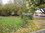


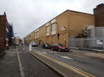


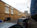

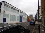
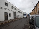
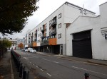
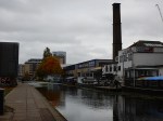



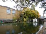
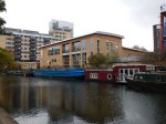
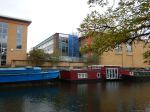
I can’t see any obvious reason, why the Leisure Centre would be used for Crossrail 2, as neither of the commercial buildings in Eagle Wharf Road are of the finest quality and given Crossrail’s treatment of Mile End Park, there would appear no reason the corner of the Park can’t be used.
One of the great advantages of the Park, would be that if you need to bring in some really heavy equipment, you’d just remove the iron railings and roll it through the gap.
Under current plans, there would appear to be no reason to extract or insert a tunnel boring machine in the Shoreditch area.
But choosing the Park would allow this to be done if required.
There is also the problem of a head-house.
It might be difficult to provide one in the Park, but evacuating into a large park from a problem in the tunel might be very safe.
Head houses on the sites in Eagle Wharf Road could even be built into any new buildings on the site.
Architecture and engineering design is moving on apace and who knows what will be possible when Crossrail 2 is built?
Electrification Of Britain’s Railways Isn’t Easy
There are a lot of reports in the media talking about the delays in electrifying railways in the UK, like this report in the Yorkshire Post, which talks about the Trans Pennine and Midland Main Line schemes.
I have just found this report in the Rail Engineer, which talks about a forty-four day closure of the important Winchburgh Tunnel between Edinburgh and Glasgow to prepare for electrification as part of the Edinburgh Glasgow Improvement Program. The report starts with this paragraph.
A legacy of the rapid early growth of Britain’s railway network is that the UK has one of the world’s most restrictive loading gauges. As a result, typically half of the cost of British electrification projects is the civil engineering work to adapt structures to provide clearance for wires and pantographs.
As anybody who’s ever got to grips with any old building, what it looks like on the surface is very different to what is underneath.
The project described in the article is challenging to say the least. This extract describes the building of the tunnel.
Winchburgh tunnel lies at the eastern end of a five- kilometre long cutting. It is 338 metres long and was opened in 1842, having taken two years to complete. When digging the cuttings and tunnel, the contractor, Gibb and Sons, removed 200,000 tons more rock than expected and consequently made a loss.
The tunnel was cut through dolerite rock, mudstone and shale. In the middle on the nineteenth century, these oil shale deposits once made West Lothian one of the world’s biggest oil producers. This shale was also a factor in an unfortunate accident during tunnel construction in 1839 when a man was severely burnt by firedamp.
The cutting is crossed by two streams, west of the tunnel. A twin four-foot diameter cast-iron inverted syphon was provided to carry Myers Burn under the railway. Swine Burn crosses the cutting on an aqueduct that had to be re-decked as part of the EGIP electrification works. Downstream of the aqueduct is a pumping station, which drains the cutting west of the tunnel. This is an area with significant drainage issues, some of which are addressed by the tunnel works.
So making it large enough for electrification wasn’t easy. As is typical on a project such as this, concrete slab track was used. You don’t see it much on UK railways, as where it is used is generally in tunnels and other places, where you have tight clearances.
In the Winchburgh tunnel slab track was used and they are also using an overhead rail system to get the power to the train.
In searching for a good article about slab track, I found this article on Balfour Beatty’s Rail web site, which is entitled Polyurethane Slab Track.
Balfour Beatty have worked with Herriot Watt University to create a method of using polyurethane to create a method for strengthening track in awkward places.
One example describes how a bridge was improved to cope with modern loads.
While George Stephenson was a forward thinker, even he didn’t predict freight trains running at 80mph with 25 tonne axle loads over his bridge. So he hadn’t calculated for those stresses. The bridge has done a good job of coping with them for 190 years, but it was getting a bit tired.
The article also highlights that Network Rail has 25,000 masonry arches, so you can see why there must be a need for such a technique.
The technique has also been used to increase the headrom for electrification in a tunnel on the Midland Main Line.
It’s all impressive engineering.
A Circular Walk From Royal Oak Station
When I wrote about my last visit to Royal Oak and the Westbourne Park Footbridge in October last year, I said this.
It will be fascinating to go back here, to see the area, as the railway and its infrastructure progresses.
So this morning, I went back and took these pictures, to see if they could add to what I saw yesterday.
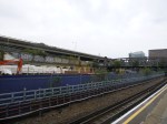
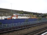
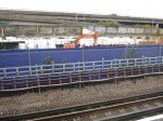
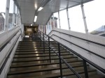
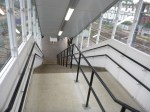

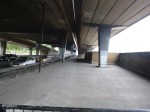
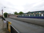


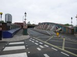
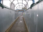
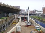
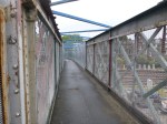
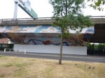
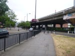
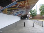

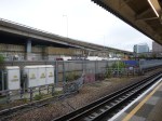


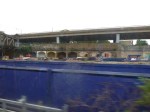
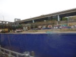
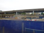
Things have moved on apace.
1. Royal Oak station is no longer the rusting ruin it was last year and all of the glass is now clear and immaculate.
2. Crossrail has also dropped the height of the blue security fence, which means tall people can get good pictures of the Crossrail site from the platform of Royal Oak station.
3. It is now clear that the arches support the slip road up to the Westway and that they may have once supported an old railway line.
4. I was pleased to see the lith-style information displayed in a poster. It must help with putting information in places, which are too small or not suitable for a full size lith. It all goes to show how good, Legible London is.
According to Wikipedia, it is now the world’s largest pedestrian wayfinding project. So if Ipswich can have one, why can’t any number of important capital and tourist cities.
5. Crossrail’s Royal Oak Portal is now clearly visible from the Westbourne Park Footbridge and the pictures show what a tight squeeze the double-track railway is between the Westway and the Metropolitan Line.
6. I don’t think it will be long before they start laying track, as this will make it easier to get men and materials in and out of the tunnels.
7. I have read that between the portal and the existing bus garage, the area will be used to store trains and also turn back those running to Paddington. The bus garage extension is being built over the sidings.
Crossrail is certainly coming together in Westbourne Park, where it squeezes between the Westway and the Great Western Main Line.
Jubilee Line Vent Shaft At Durand’s Wharf
The pictures show the ventilation and access shaft at Durand’s Wharf for the Jubilee Line.




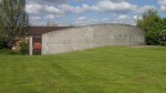
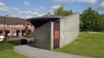
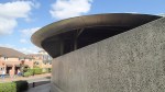

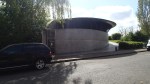

It is certainly a much more subtle and smaller design than the shafts for the Channel Tunnel Rail Link.
This Google Earth image shows that it fits well into the small park.
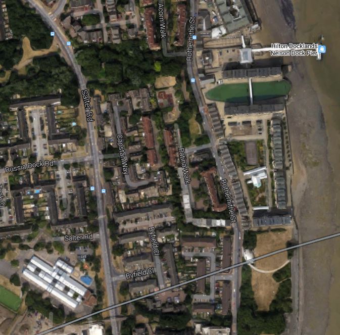
Durand’s Whaft Vent Shaft
It’s just by the silver line, which marks the Jubilee Line.
Removing One Hundred And Seventy Years Of Inadequate Design
The Manchester to Preston railway is san important line in the North-West of England, that was completed in 1841.
To say that is not fit for purpose is a total understatement, as it is not electrified and has a speed limit of just seventy-five miles per hour.
Finally, the line is being electrified and the speed limit will be raised to a hundred. From December 2016, hopefully refurbished Class 319 trains will be speeding from Manchester via Bolton and Preston to Blackpool and possibly Windermere.
The major problem on the line are the twin tunnels at Farnworth. They have a history of make-do-and-mend and are too small to take the overhead wires and Network Rail have come up with a practical solution, that should last several hundred years at least. This Google Earth image shows the ends of the tunnels with respect to the location of Farnworth station and the A666.
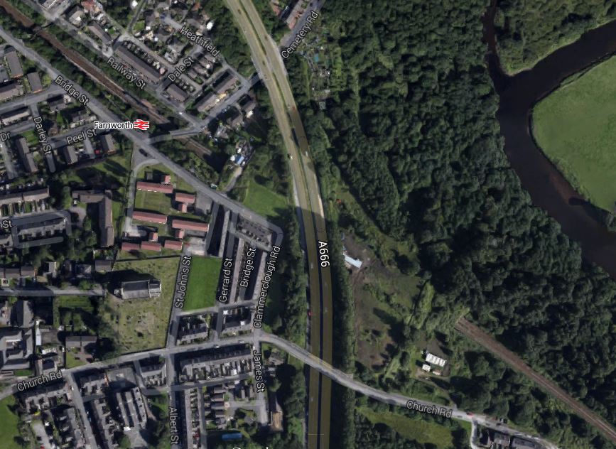
Farnworth Station And Tunnels
The smaller of the two tunnels will be refurbished and given a concrete lining, so that during the works, there will always be one track for trains. They will then bore out the larger tunnel, so that it is big enough to take two tracks and the overhead lines.
This will require that between May and October this year, there will be significant disruption to rail passengers. The whole project is described in this article in the Bolton News. It may cause a lot of disruption, but the passengers seem philosophical, as these paragraphs from the article show..
Jeff Davies, part of the newly formed Bolton Rail Users Group, said: “The station closures are the bad news, but there is good news here actually.
“It is the beginning of big investment which could take us out of the present problems and the companies have been at great pains to minimise inconvenience and ensure that Bolton people who work in Manchester will still be able to get there.
Perhaps this is because Network Rail have done their public relations well, if this YouTube video entitled Rebuilding the Farnworth Tunnel is anything to go by.
It all goes to prove that politicians should have sorted out the mess that are the railways of the North many years ago.
Pudding Mill Lane Portal – 17th April 2015
Crossrail’s Stratford Portal is where the surface section of the line to Shenfield enters the tunnel to go to Whitechapel and all the stations to the west. This is a Google Earth image of the works at the tunnel portal.
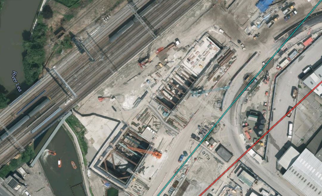
Crossrail’s Stratford Portal
A ramp is being built to and from the Great Eastern Main Line to connect the Crossrail tracks to those of the main line. This picture shows how Pudding Mill Lane station will look, when everything is complete.
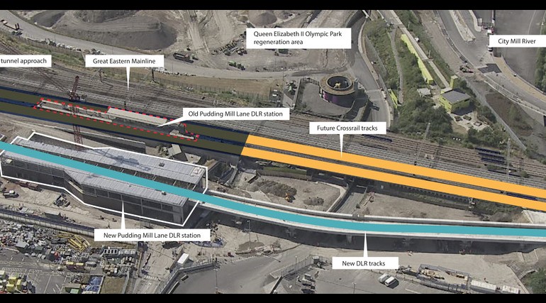
Pudding Mill Lane Station
The Crossrail tracks are shown in yellow and the DLR ones in blue.
These pictures of the area were taken from Pudding Mill Lane station or a DLR train.
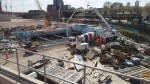
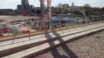
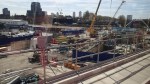
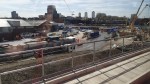
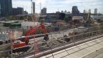

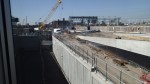
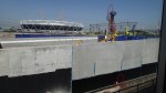
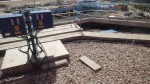
The station is certainly a good place to go to see the works going on here.

