Scotland’s Energy Storage
I have been using the web sites of Drax Group, SSE Renewables and ILI Group, and this page from Strathclyde University to look at various hydro-electric schemes to store energy using the tried-and-tested method of pumped hydro.
I have analysed these schemes.
Affric/Beauly
The scheme is now owned by SSE Renewables and has a page on their web site, which introduces the scheme like this.
Situated about 16 kilometres to the west of Inverness, Beauly is the gateway to the Affric/Beauly hydro electric scheme.
Currently, it generates a maximum power of 100.3 MW.
My analysis in Repurposing The Affric/Beauly Hydro-Electric Scheme, showed the following.
- Research from Strathclyde University, says that the Affric/Beauly scheme could support 78 GWh of pumped storage in one scheme at Fasnakyle.
- Adding pumped storage facilities to the Affric/Beauly hydro-electric scheme, with a capacity of upwards of a conservative 50 GWh, should be possible.
Generating capacity and system operation could be improved by replacing some or all of the 1950s and 1960s turbines with modern units and using modern control systems.
The Affric/Beauly hydro-electric scheme could be augmented by upwards of 50 GWh of storage.
Balliemeanoch
This new scheme is being developed by the ILI Group.
From what is published in the press. it appears to be a giant 1.5 GW/45 GWh project.
In Thoughts On The Balliemeanoch Pumped-Hydro Scheme, I analyse the plan.
The Balliemeanoch hydro-electric scheme could add 45 GWh of storage.
Balmacaan
This new scheme is being developed by SSE Renewables.
My searches in A Possible Balmacaan Pumped Storage System, showed the following.
It has a 600 MW generating capacity and I suspect would have about 15-20 GWh of storage.
The Balmacaan hydro-electric scheme could conservatively add upwards of 15 GWh of storage.
Breadalbane
The scheme is now owned by SSE Renewables and has a page on their web site, which introduces the scheme like this.
The Breadalbane scheme is set in the mountainous region around Loch Lyon, Loch Tay and Loch Earn in Perthshire.
Currently, it generates a maximum power of 168.4 MW.
My analysis in Repurposing The Breadalbane Hydro-Electric Scheme, showed the following.
- Research from Strathclyde University, says that the Breadalbane scheme could support 12 GWh of pumped storage in one scheme at Ben Lawers.
- I believe a similar scheme could be built South of Loch Tay to add a similar amount of pumped storage capacity.
As with the Beauly/Affric scheme, generating capacity and system operation could be improved by replacing some or all of the 1950s and 1960s turbines with modern units and using modern control systems.
The Breadalbane hydro-electric scheme could be augmented by upwards of 12 GWh of storage.
Coire Glass
This new scheme is being developed by SSE Renewables and the project has its own web site, which introduces the scheme like this.
Coire Glas is a hydro pumped storage scheme with a potential capacity of up to 1500MW. Coire Glas is an excellent pumped storage site with a large lower reservoir (Loch Lochy) and a significant elevation of more than 500m between the lower and the new upper reservoir site over a relatively short distance.
It is planned to generate a maximum power of up to 1.5 GW for twenty hours, which indicates an energy storage capacity of 30 GWh.
In SSE Renewables Launches 1.5GW Coire Glas Construction Tender, I talk about the current status of the project.
The Coire Glas hydro-electric scheme could add 30 GWh of storage.
Conon
The scheme is now owned by SSE Renewables and has a page on their web site, which introduces the scheme like this.
The Conon scheme lies within the northwest Highlands, broadly between Inverness and Ullapool. Electricity generation started here when the Ross-shire Electricity Supply Company built the small Falls of Conon hydro electric power station in the 1920s.
Currently, it generates a maximum power of 107.2 MW.
My analysis in Repurposing The Conon Hydro-Electric Scheme, showed the following.
- Research from Strathclyde University, says that the Conon scheme could support up to 131 GWh of pumped storage.
- Adding pumped storage facilities to the Conon hydro-electric scheme, with a capacity of upwards of a conservative 30-40 GWh, should be possible.
As with other schemes, generating capacity and system operation could be improved by replacing some or all of the 1950s turbines with modern units and using modern control systems.
The Conon hydro-electric scheme could be augmented by upwards of 30 GWh of storage.
Corrievarkie
This new scheme is being developed by the ILI Group.
From the planning application it appears to be a 600 MW/14.5 GWh project.
In Corrievarkie Pumped Storage Hydro Project, I analyse the plan.
The Corrievarkie hydro-electric scheme could add 14.5 GWh of storage.
Cruachan
Cruachan is a pumped-storage power station, that is owned by Drax, which have a comprehensive web site for the power station.
- It has an output of 440 MW.
- It has an energy storage capacity of 7.1 GWh
- It can can reach full generating capacity in less than 30 seconds.
In Drax’s Plans For Cruachan, I analyse Drax’s plans, which they call Cruachan 2.
- It will be a 600 MW power station.
- It will be to the East of the current power station.
- More than a million tonnes of rock would be excavated to build the power station.
The existing upper reservoir, which can hold 2.4 billion gallons of water, has the capacity to serve both power stations.
These was my conclusions.
It looks like very good engineering to me.
- There is a good chance, that on most nights, the reservoir will be filled using wind energy
- The maximum output of the Cruachan power station has been more than tripled from 323 to 1010 MW.
- There has been no increase in the size of the Cruachan reservoir.
Scotland will now have a GW-sized hydro-electric power station.
It will not be very much smaller than Sizewell B nuclear station.
Foyers
The scheme is now owned by SSE Renewables and has a page on their web site, which introduces the scheme like this.
The current Foyers Power Station operates quite differently to conventional hydro electric power stations. Foyers hydro scheme consists of one pumped hydro power station and one hydro power station and one major dam..
Currently, it generates a maximum power of 305 MW.
My research and analysis in The Development Of The Foyers Pumped Storage Scheme, showed the following.
- Foyers is a modern pumped-hydro scheme with a capacity of 10 GWh.
- The updating of the original 1896 hydro-power station to a modern pumped-storage system in 1974 is a superb example of hydro-power engineering.
The development of Foyers power station is an example, that shows what can be done in other hydro-electric schemes around Scotland and the rest of the world.
Galloway
Galloway is a hydroelectric scheme, that is owned by Drax, which have a comprehensive web site for their two hydroelectric schemes in Scotland; Galloway and Lanark.
- Galloway has a total output of 109 MW.
- It has six power stations at Drumjohn, Kendoon, Carsfad, Earlstoun, Glenlee and Tongland.
- There is no energy storage
- It is what is known as a run-of-the-river scheme.
The scheme opened in the 1930s.
Glendoe
The scheme is now owned by SSE Renewables and has a page on their web site, which introduces the scheme like this.
In 2009, the first major hydro electric power station to be built in Scotland for almost 30 years, Glendoe on the eastern shore of Loch Ness, began generating electricity.
Currently, it generates a maximum power of 106.5 MW.
My analysis in Glendoe Hydro Power Station, led me to conclude, that engineers will look at this scheme built in the early years of this century to convert it to a pumped storage facility. It might even have been designed for conversion to a pumped storage station, as it was built after the successful conversion of Foyers power station. Comparing the size of the upper lake to Foyers and other schemes, I would estimate it could easily provide in excess of 15 GWh of storage.
The Glendoe hydro-electric scheme could be augmented by upwards of 15 GWh of storage.
Glenmuckloch
This is a small scheme promoted by Buccleuch, that generates 4 MW and stores 1.6 GWh in a disused opencast coal mine.
My analysis in The Glenmuckloch Pumped Storage Scheme, led me to this conclusion.
This project appears to have stalled, but I do like the idea of using a disused mine to store energy and the engineering behind the project.
I will ignore it in my conclusions of this post.
Great Glen
The scheme is now owned by SSE Renewables and has a page on their web site, which introduces the scheme like this.
The Great Glen runs for more than 100 kilometres from Inverness in the northeast, to Fort William in the southwest, following a geological fault line that divides north and south Scotland.
Currently, it generates a maximum power of 112.7 MW.
My analysis in Repurposing The Great Glen Hydro-Electric Scheme, showed the following.
- Research from Strathclyde University, says that the Great Glen scheme could support up to 90 GWh of pumped storage.
- Adding pumped storage facilities to the Great Glen hydro-electric scheme, with a capacity of upwards of a conservative 30 GWh, should be possible.
As with other schemes, generating capacity and system operation could be improved by replacing some or all of the 1950s and 1960s turbines with modern units and using modern control systems.
The Great Glen hydro-electric scheme could be augmented by upwards of 30 GWh of storage.
Lanark
Lanark is a hydroelectric scheme, that is owned by Drax, which have a comprehensive web site for their two hydroelectric schemes in Scotland; Galloway and Lanark.
- Lanark has a total output of 17 MW.
- It has two power stations at Bonnington and Stonebyres.
- There is no energy storage
- It is what is known as a run-of-the-river scheme.
The scheme opened in the 1920s.
Red John
This new scheme is being developed by ILI Group and the project has its own web site, which introduces the scheme like this.
Between 2007 and 2015, the total installed capacity of renewables electricity in Scotland has more than doubled. Due to its intermittent nature, the rise in renewable generation has resulted in increased demand for flexible capacity to help meet energy balancing requirements for the national grid system.
Pumped storage hydro is considered by the Directors to be the most developed and largest capacity form of grid energy storage that currently exists. This can help reduce renewable energy curtailment and therefore promote grid stability.
The web site says this about the project.
- The scheme has an output of 450 MW.
- The storage capacity is 2.8 GWh.
- The scheme has planning consent.
- The project is budgeted to cost £550 million.
- The construction program indicates that the scheme will be completed by the end of 2025.
It also has very detailed maps.
I wrote about the project in Red John Pumped Storage Hydro Project, where I came to these conclusions.
- This scheme has the output of a large gas-fired power station for just over six hours.
- The finances must add up, as no-one would back a scheme like this if they didn’t get an adequate return on their money.
It may only be a small scheme, that is a quarter of the size of the existing nearby Foyers pumped-storage scheme, but as it is shovel-ready, we should start digging.
The Red John hydro-electric scheme would add 2.8 GWh of storage.
Shin
The scheme is now owned by SSE Renewables and has a page on their web site, which introduces the scheme like this.
Shin is Scotland’s most northerly hydro electric scheme. It utilises water from a 650 square kilometre catchment area in Sutherland, including Loch Shin, and water from the River Cassley and River Brora.
Currently, it generates a maximum power of 32.1 MW.
My analysis in Shin Hydro Power Scheme, showed the following.
- I would be very surprised if any pumped storage were to be added to this scheme.
- This 1950s scheme has been partially updated.
Perhaps some more updating would be worthwhile.
Sloy/Awe
The scheme is now owned by SSE Renewables and has a page on their web site, which introduces the scheme like this.
With the exception of Cruachan Power Station which was commissioned in 1965, major work on the Sloy/Awe scheme was completed by 1963, the year the Beatles had their first No 1 hit with From Me To You – and a world away from the immediate post-war austerity being experienced when Sloy Power Station was commissioned just 14 years earlier.
Currently, it generates a maximum power of 261.9 MW.
My analysis in Repurposing The Sloy/Awe Hydro-Electric Scheme, showed the following.
- Research from Strathclyde University, says that the Sloy/Awe scheme could support up to 68 GWh of pumped storage.
- Adding pumped storage facilities to the Sloy/Awe hydro-electric scheme, with a capacity of upwards of a conservative 40 GWh, should be possible.
As with other schemes, generating capacity and system operation could be improved by replacing some or all of the 1930s and 1950s turbines with modern units and using modern control systems.
The Sloy/Awe hydro-electric scheme could be augmented by upwards of 40 GWh of storage.
Tummel Valley
The scheme is now owned by SSE Renewables and has a page on their web site, which introduces the scheme like this.
The Tummel scheme stretches from Dalwhinnie, famous for its whisky distillery, in the north, to the remote Rannoch Station in the west, and the highly-popular tourist town of Pitlochry in the east.
Currently, it generates a maximum power of 309.2 MW.
My analysis in Repurposing The Tummel Hydro-Electric Scheme, showed the following.
- Research from Strathclyde University, says that the Tummel Valley scheme could support up to 135 GWh of pumped storage.
- Adding pumped storage facilities to the Tummel Valley hydro-electric scheme, with a capacity of upwards of a conservative 40-60 GWh, should be possible.
As with other schemes, generating capacity and system operation could be improved by replacing some or all of the 1930s and 1950s turbines with modern units and using modern control systems.
The Tummel Valley hydro-electric scheme could be augmented by upwards of 40 GWh of storage.
A Simple Summary
These are deliberately conservative figures from my analysis.
- Affric/Beauly – 50 GWh
- Balliemeanoch – 45 GWh
- Balmacaan – 15 GWh
- Breadalbane – 12 GWh
- Coire Glas – 30 GWh
- Conon – 30 GWh
- Corrievarkie – 14.5 GWh
- Glendoe – 15 GWh
- Great Glen – 30 GWh
- Red John – 2.8 GWh
- Sloy/Awe – 40 GWh
- Tummel Valley – 40 GWh
Note.
- With new storage like Balliemeanoch, Balmacaan, Coire Glas, Corrievarkie and Red John, I am using published figures where they are available.
- With figures from existing schemes,I am being deliberately very conservative.
That is a total of 324.3 GWh with 107.3 GWh down to new storage
Strathclyde University’s Prediction
This page on the Strathclyde University web site, gives these figures for the possible amounts of pumped-storage that can be added to existing schemes.
- Errochty – 16
- Glasgarnock – 23
- Luichart – 38
- Clunie – 40
- Fannich – 70
- Rannoch – 41
- Fasnakyle – 78
- Tummel – 38
- Ben Lawers – 12
- Nant – 48
- Invermoriston – 22
- Invergarry – 41
- Quoich – 27
- Sloy – 20
That is a total of 514 GWh or 621.3 GWh if you include new storage.
Conclusion
Scotland and the UK, has been left a superb legacy for the future by the pioneering work of Scottish engineers and the North of Scotland Hydroelectric Board.
Most of these assets are now in the hands of two groups; Scottish and Southern Energy (SSE) and Drax Group.
Having seen several of the schemes detailed in this post, in the last few weeks, on Michael Portillo’s; Great Coastal Railway Journeys, it does seem that both groups are looking after their assets.
SSE and Drax also seem to be doing their best to publicise the success of one of the UK’s high-value, but low-profile engineering assets.
I believe that we should do a survey that would identify the following.
- What needs to be done to allow each aqueduct, dam, power station and tunnel to continue to function until a given date in the future.
- Which of the individual schemes can be updated to larger schemes or pumped storage systems.
We would then be able to device a long term plan to create a world-class hydro-electric power scheme for Scotland.
Scotland should be able to provide upwards of 400 GWh of pumped-storage.
This article on Current News is entitled Up To 24GW Of Long Duration Storage Needed For 2035 Net Zero Electricity System – Aurora.
These are the first three paragraphs.
Deploying large quantities of long duration electricity storage (LDES) could reduce system costs and reliance on gas, but greater policy support is needed to enable this, Aurora Energy Research has found.
In a new report, Aurora detailed how up to 24GW of LDES – defined as that with a duration of four hours or above – could be needed to effectively manage the intermittency of renewable generation in line with goals of operating a net zero electricity system by 2035. This is equivalent to eight times the current installed capacity.
Additionally, introducing large quantities of LDES in the UK could reduce system costs by £1.13 billion a year in 2035, cutting household bills by £26 – a hot topic with energy bills on the rise as a result of high wholesale power prices.
The report also says that long duration storage could cut carbon emissions by ten million tonnes of carbon dioxide per year.
It appears to me, Scotland can provide more than enough energy storage for the UK and the Island of Ireland, even if the seas around the British Isles were almost completed covered by wind turbines.
In addition, to the works in Scotland to update the various hydroelectric schemes, there would need to be more interconnectors around the UK and probably to close countries like Belgium, Denmark, France, Germany, the Netherlands and Norway.
There could even be an interconnector between Iceland and Scotland, so Iceland’s abundance of zero-carbon electricity could be exported to Europe.
Repurposing The Breadalbane Hydro-Electric Scheme
The Breadalbane hydro-electric scheme was built in the 1950s and early 1960s, by the North of Scotland Hydroelectric Board.
- The scheme is now owned by SSE Renewables and has a page on their web site.
- There are seven individual power stations; Lubreoch, Cashlie, Lochay, Finlarig, Lednock, St Fillans and Dalchonzie.
- There are five dams; Lawers, Breaclaich, Lednock, Lubreoch and Giorra.
This map from the SSE Renewables web site shows the layout of the dams and power stations.
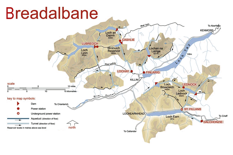
The sizes of the power stations in the scheme are as follows.
- Lubreoch – 4 MW
- Cashlie – 11 MW
- Lochay – 45 MW
- Finlarig – 16.5 MW
- Lednock – 3 MW
- St Fillans – 16.8 MW
- Dalchonzie – 4 MW
This gives a total power of 100.3 MW.
This Google Map shows Loch Tay.
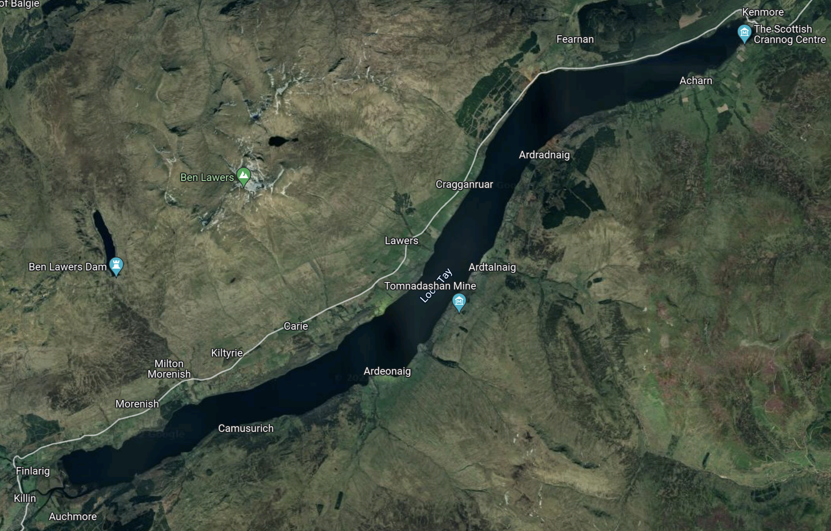
Note
- Finlarig. where there is a power station, with a capacity of 16.5 MW.
- Ben Lawers dam, is to the West of Ben Lawers and is marked by a blue arrow.
- The biggest power station in the scheme is Lochay power station, which has a capacity of 45 MW.
- Lochay power station is to the West of Finlarig power station and both appear to be fed from Ben Lawers dam and others to the North.
This Google Map shows Loch Earn.
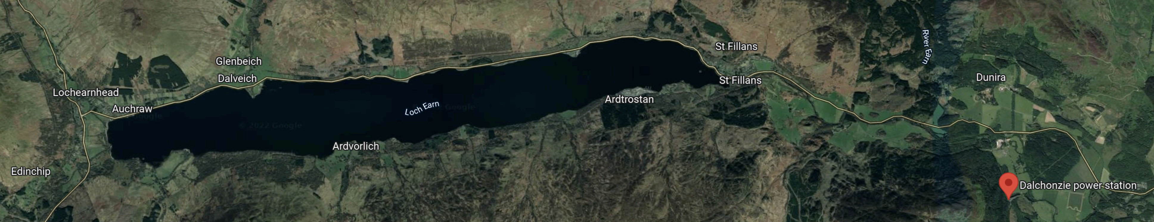
Note.
- Loch Earn is South of Loch Tay
- The red arrow indicates Dalchonzie power station.
- Dalchonzie power station has a generating capacity of only 4 MW.
This Google Map shows the location of Loch Lednoch between Loch Tay and Loch Earn.
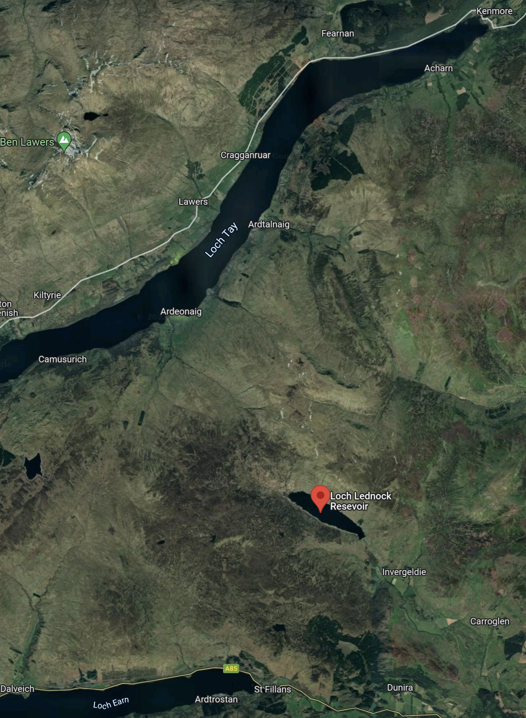
Note that Lednoch has the 3 MW Lednoch power station at its Northern end.
This map shows to the West of Ben Lawers.
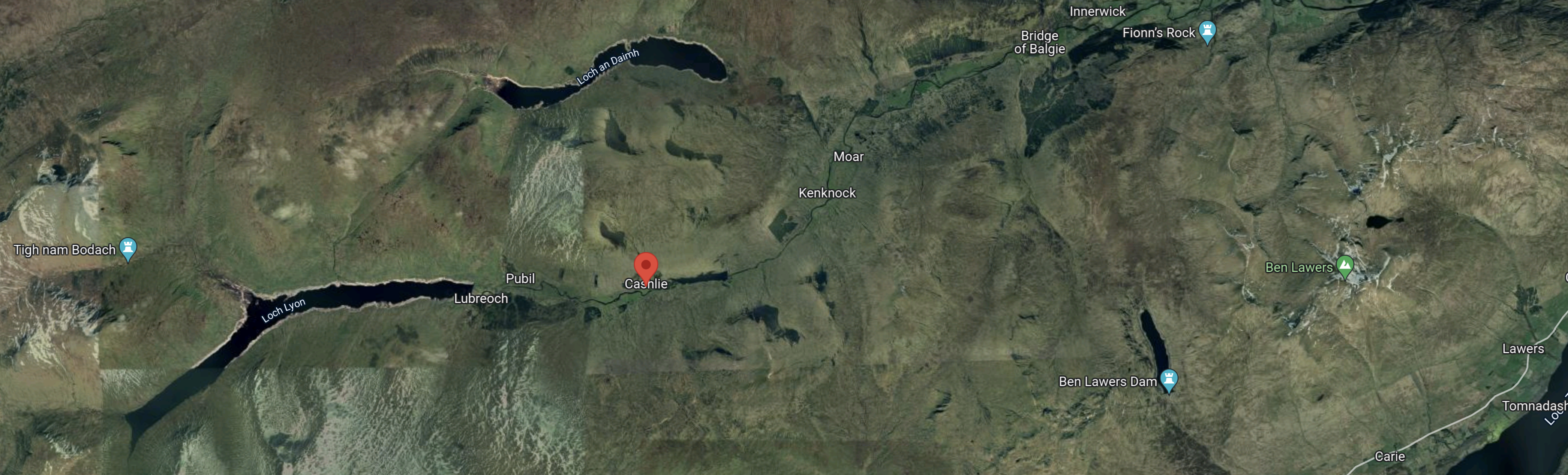
The red arrow indicate the rough location of the 11 MW Cashlie power station.
Is The Breadalbane Scheme Complete?
Looking at the dates of power station construction, I wonder if the dam builders concentrated in the early 1960s on the construction of Cruachan pumped storage station, which was constructed between 1959 and 1965.
Also to me, the Breadalbane scheme seems to have a lot of power stations and tunnels for just over 100 MW.
- At Rannoch, there is a 44 MW power station on the shores of Loch Rannoch, that was built in 1930.
- At Sloy there is a 152.5 MW power station on the shores of Loch Lomond, that was built in 1950.
I would have thought that a progression from Sloy, would have seen a large power station built on the shores of Loch Tay, whereas Lochay power station is only 44 MW.
This Google Map shows Lochan Breaclaich, which is a lake created by the construction of Breaclaich dam.
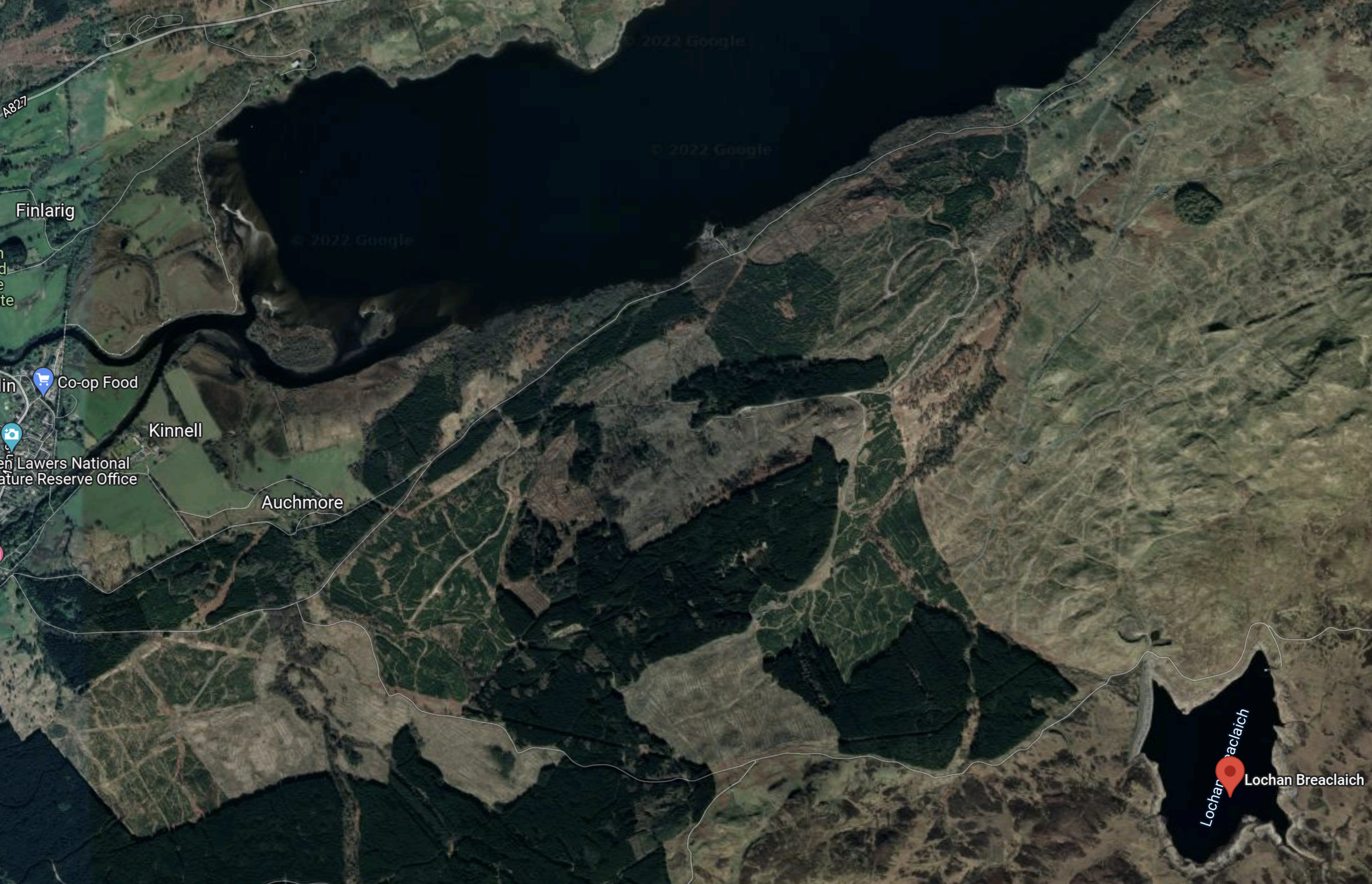
Lochan Breaclaich is marked by the red arrow and it is Loch Tay at the top of the map.
This page on the Canmore web site gives these details of Lochan Breaclaich and its dam.
Breaclaich dam is designed to prevent Loch Breachlaich and a number of other intakes from discharging into the Loch Tay catchment. A tunnel intake gatehouse is upstream of the dam and takes water via tunnel and pipeway through to Lednock power station.
The SSE map shows this tunnel to the North-Western end of Loch Lednoch, where the Lednoch power station is located.
It seems a lot of work was done to feed the power station, which has a capacity of just 3 MW.
Was it originally intended that Lochan Breaclaich would have fed a large power station on the Southern shore of Loch Tay?
Strathclyde University And Pumped Storage Power For Scotland
This page on the Strathclyde University gives a list of the pumped storage potential for Scottish hydrogen-electric dams and power stations.
These figures are given for the dams and lochs in the Breadalbane scheme.
- Ben Lawers – 12 GWh
It would appear that based on research from Strathclyde University, that the Breadalbane scheme could support 12 GWh of pumped storage.
Could this be augmented by a pumped-storage scheme from the Southern shore of Loch Tay to Lochan Breaclaich?
- Lochan Breaclaich is at an altitude of 443 metres.
- Loch Tay is at an altitude of 106 metres.
- Foyers pumped storage has a capacity of 300 MW and a head of 179 metres.
If a 12 GWh pumped storage system can be built on the North side of Loch Tay, I can’t see why with a head of 337 metres, one can’t be built on the South side of the Loch.
Was this the original plan?
Water Flows In The Breadalbane Scheme
Looking at the SSE Renewables map of the Great Glen scheme, water flows appear to be as follows.
- Loch an Daimh to Stronuich Reservoir via Cashlie power station
- Loch Lyon to Stronuich Reservoir via Lubreoch power station
- Stronuich Reservoir to Lochay power station
- Loch Ben Lawers to Finlarig power station
- Lochan Breaclaich to Loch Lednock via Lednoch power station
- Loch Lednock to Loch Earn via St. Fillans power station
- Loch Earn to Dalchonzie power station
It seems to be an expensive scheme with lots of tunnels and an underground power station at St. Fillans.
Refurbishing And Repurposing The Breadalbane Scheme
Perhaps as the power stations are now over fifty years old, one simple way to increase the generating capacity of the Breadalbane scheme, might be to selectively replace the turbines, with modern turbines, that can generate electricity more efficiently.
I suspect that SSE Renewables have an ongoing program of improvements and replacements for all of their hydro-electric stations in Scotland. Some turbines at Sloy power station have already been replaced with larger ones.
Adding Pumped Storage To The Breadalbane Scheme
In this list of Scotland’s lochs on Wikipedia, there is a short list of the largest and deepest lochs.
- The first five are Loch Ness, Loch Lomond, Loch Morar, Loch Tay and Loch Awe.
- Loch Ness has the Foyers pumped-storage scheme and others are in development.
- Loch Awe has the Cruachan pumped-storage scheme.
- Loch Lomond has the Sloy pumped-storage scheme in development.
- Loch Morar is used in the Lochaber hydro-electric scheme.
It seems to me, that Loch Tay could support some pumped-storage, just because of its size.
Strathclyde University have identified that Ben Lawers can support 12 GWh on the North side of Loch Tay.
Could a scheme involving Lochan Breaclaich add a similar amount of pumped-storage on the South side of Loch Tay?
I also suspect there are possibilities for adding pumped-storage to and from Stronuich Reservoir.
Conclusion
I believe that Breadalbane is an incomplete scheme and that pumped-storage could convert this scheme into a much more powerful and larger scheme.
There would appear to be two schemes, that could each add around 12 GWh of pumped storage.
One advantage is that the waters of Loch Tay can be used for the lower reservoir.
The Coire Glas Pumped Storage Scheme
The Coire Glas pumped storage scheme, which is being developed by SSE Renewables will be the first large scale pumped storage scheme to be developed in the UK for more than 30 years.
- It would have a power output of 1.5 GW.
- Compared to Dinorwig (Electric Mountain) in Wales at 9.1 GWh and Cruachan in Scotland at 7.1 GWh, it will be a giant.
- Planning permission has been obtained.
The Coire Glas project has a web site.
This is the introductory paragraph.
Coire Glas is a hydro pumped storage scheme with a potential capacity of up to 1500MW. Coire Glas is an excellent pumped storage site with a large lower reservoir (Loch Lochy) and a significant elevation of more than 500m between the lower and the new upper reservoir site over a relatively short distance.
There is also an explanatory video.
This map was clipped from this SSE planning document.
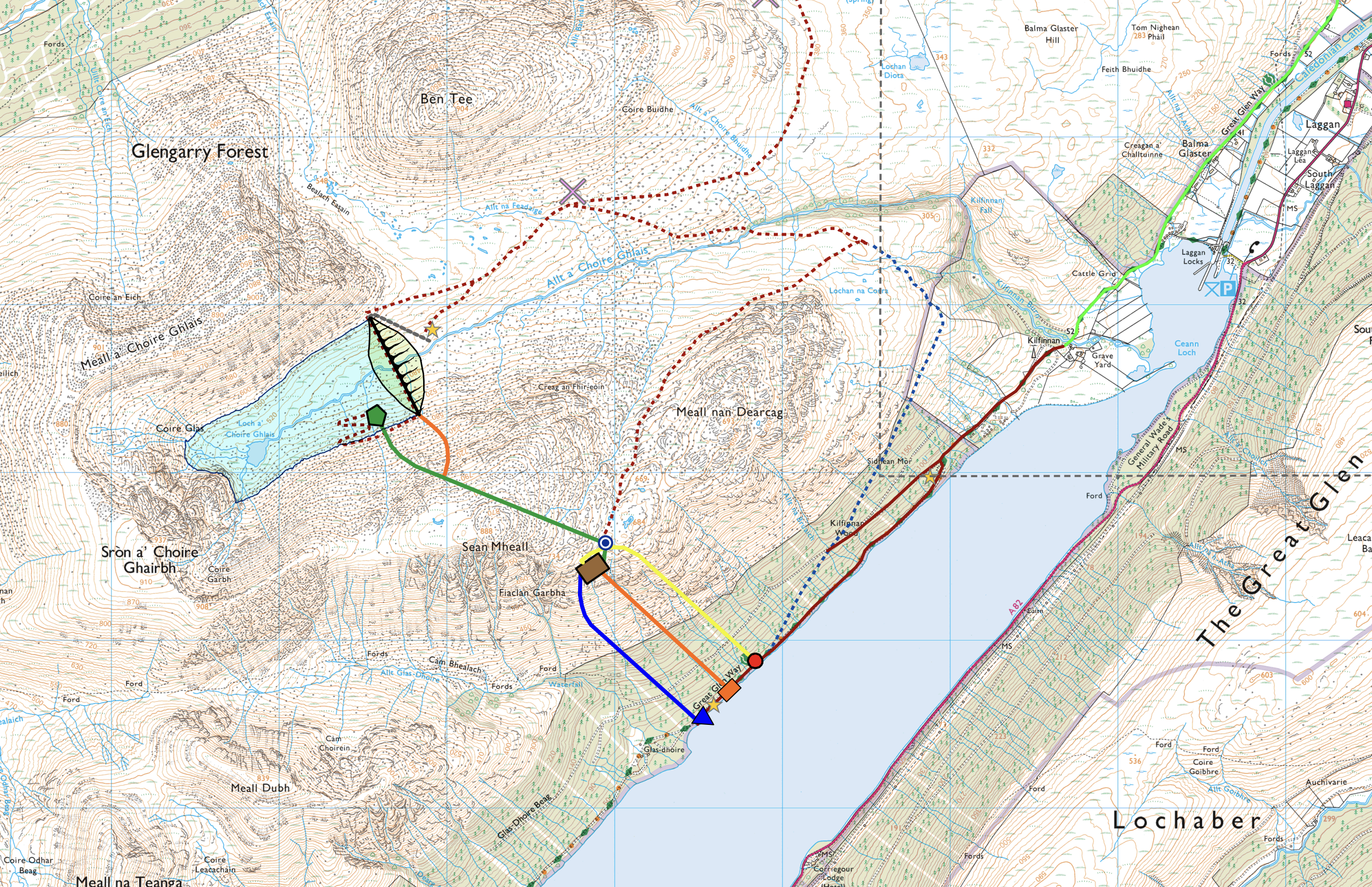
Note.
- Loch Lochy in the Great Glen will be the lower reservoir.
- Loch Lochy is a freshwater loch, that is up to seventy metres deep.
- The top reservoir is formed by building a dam across the stream, that runs into the Northern end of Loch Lochy.
- The green line leading from the pentagon in the lake behind the dam towards Loch Lochy is the headrace tunnel.
- It leads to the brown rectangle, which is the underground power station.
- The blue line leading from the power station, where water is discharged into the loch.
- The two orange lines are access tunnels.
- The yellow line is the emergency access tunnel.
It is a standard layout for a pumped storage power station.
- To store electricity, water is pumped from Loch Lochy and stored in the new lake.
- To generate electricity, water runs down the headrace tunnel, through the turbines and then down the tailrace into Loch Lochy.
- The power station would have a number of pump/turbines, that can do both tasks.
In addition, any water from rain or snow melt, that runs into the top lake gives low-cost extra electricity.
This layout of the dam and the upper lake was clipped from this SSE planning document.
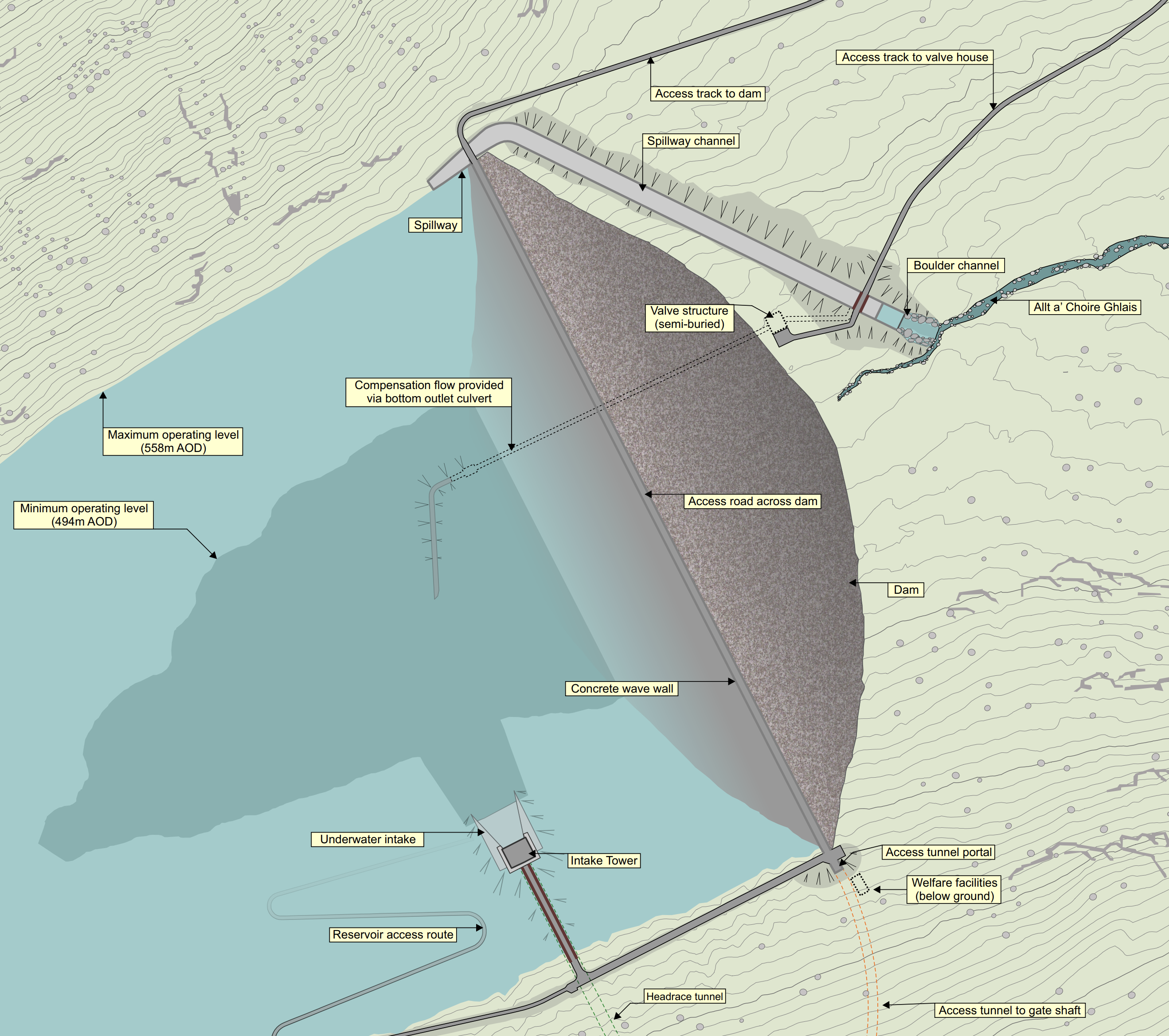
It would be an impressive structure.
Could this pumped storage scheme give the UK energy security?
Repurposing The Great Glen Hydro-Electric Scheme
The Great Glen hydro-electric scheme was built in the 1950s and early 1960s, by the North of Scotland Hydroelectric Board.
- The scheme is now owned by SSE Renewables and has a page on their web site.
- There are six individual power stations; Ceannacroc, Livishie, Glenmoriston, Quoich, Invergarry and Mucomir.
- There are five dams; Cluanie, Loyne, Dundreggan, Quoich and Invergarry.
This map from the SSE Renewables web site shows the layout of the dams and power stations.
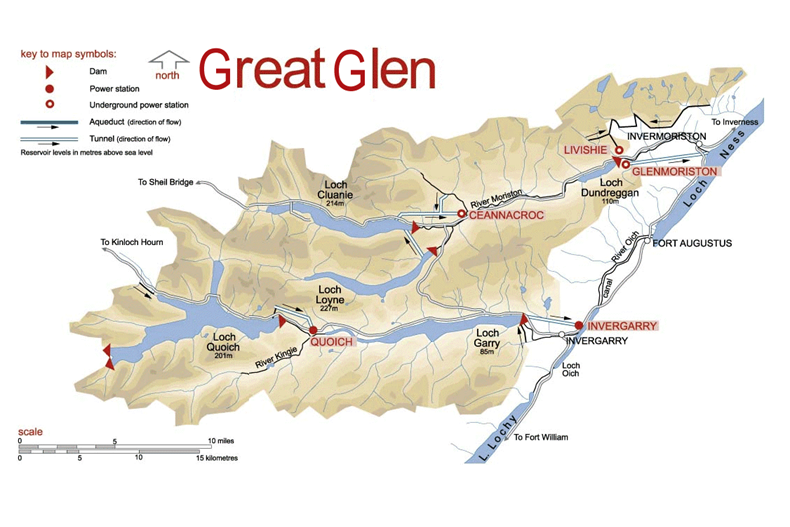
The sizes of the power stations in the scheme are as follows.
- Ceannacroc – 20 MW
- Livishie – 15 MW
- Glenmoriston- 37 MW
- Quoich – 18 MW
- Invergarry – 20 MW
- Mucomir – 1.7 MW
This gives a total power of 112.7 MW.
This Google Map shows the same area as the SSE Renewables Map.
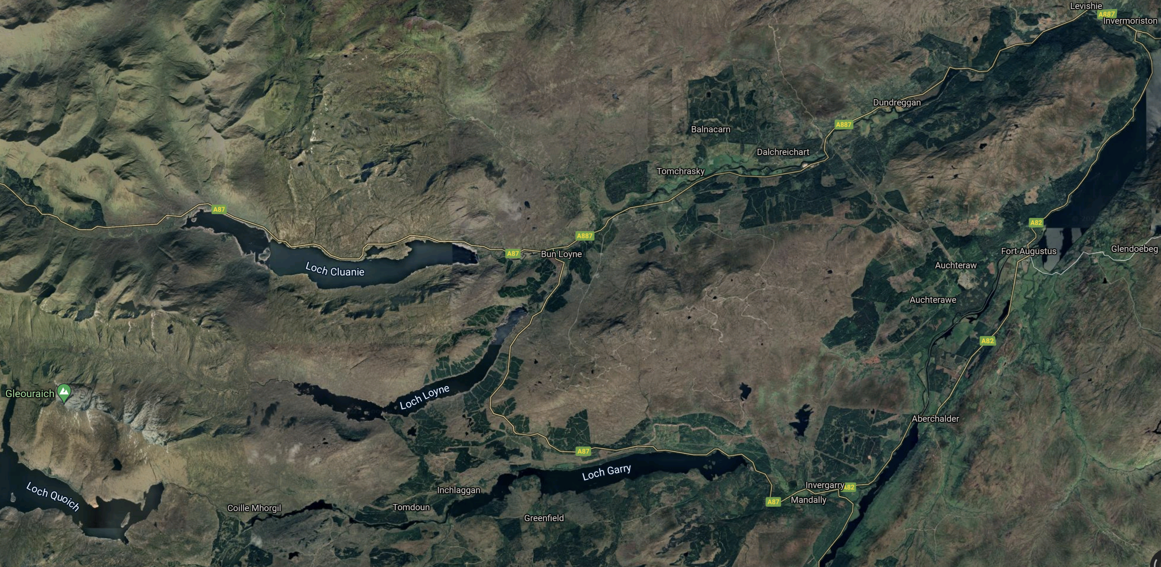
Note.
- Loch Quoich is in the South-West corner.
- To the East of Loch Quoich is Loch Garry and to the North-East is Loch Loyne.
- Loch Cluanie is to the North.
- Invermoriston is in the North-East corner.
The scheme also includes three underground power stations and several miles of tunnels.
Strathclyde University And Pumped Storage Power For Scotland
This page on the Strathclyde University gives a list of the pumped storage potential for Scottish hydrogen-electric dams and power stations.
These figures are given for the dams and lochs in the Great Glen scheme.
- Invergarry – 22 GWh
- Glenmoriston- 41 GWh
- Quoich – 27 GWh
It would appear that based on research from Strathclyde University, that the Great Glen scheme could support up to 90 GWh of pumped storage.
Water Flows In The Great Glen Scheme
Looking at the SSE Renewables map of the Great Glen scheme, water flows appear to be as follows.
- Loch Quoich to Loch Garry via Quoich power station.
- Loch Garry to Loch Oich via Invergarry power station.
- Loch Loyne to Loch Dundreggan via River Moriston.
- Loch Cluanie to Loch Dundreggan via Ceannacroc power station and River Moriston.
- Loch Dundreggan to Loch Ness via Glenmoriston power station.
All the water eventually flows into the sea at Inverness.
Refurbishing And Repurposing The Great Glen Scheme
Perhaps as the power stations are now over fifty years old, one simple way to increase the generating capacity of the Great Glen scheme, might be to selectively replace the turbines, with modern turbines, that can generate electricity more efficiently.
I suspect that SSE Renewables have an ongoing program of improvements and replacements for all of their hydro-electric stations in Scotland. Some turbines at Sloy power station have already been replaced with larger ones.
Adding Pumped Storage To The Great Glen Scheme
I would assume that the water to pump uphill at night or when there is a surplus of electricity will come from Loch Oich or Loch Ness.
Some power stations like Glenmoriston and Invergarry might be updated to both generate electricity or pump water up hill, as is required.
Conclusion
There would appear to be up to three schemes, that could each add around 30 GWh of pumped storage.
One advantage is that the waters of Loch Ness can be used for the lower reservoir.
Repurposing The Affric/Beauly Hydro-Electric Scheme
The Affric/Beauly hydro-electric scheme was built in the 1950s and early 1960s, by the North of Scotland Hydroelectric Board.
- The scheme is now owned by SSE Renewables and has a page on their web site.
- There are six individual power stations; Mullardoch, Fasnakyle, Deanie, Culligran, Aigas and Kilmorack.
- There are seven dams; Mullardoch, Benevean, Monar, Loichel, Beannacharan, Aigas and Kilmorack.
This map from the SSE Renewables web site shows the layout of the dams and power stations.
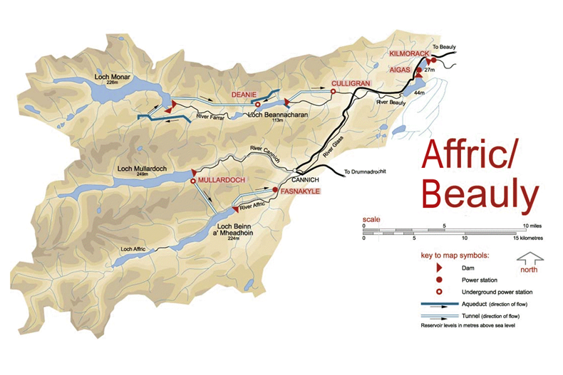
This description of the scheme is from Wikipedia.
The Affric / Beauly hydro-electric power scheme for the generation of hydro-electric power is located in the western Highlands of Scotland. It is based around Glen Strathfarrar, Glen Cannich and Glen Affric, and Strathglass further downstream.
The scheme was developed by the North of Scotland Hydro-Electric Board, with plans being approved in 1947.
The largest dam of the scheme is at Loch Mullardoch, at the head of Glen Cannich. From there, a tunnel takes water to Loch Beinn a’ Mheadhoinn (Loch Benevean) in Glen Affric, via a small underground power station near Mullardoch dam. Loch Benevean is also dammed, with a tunnel taking water to the main power station of Fasnakyle, near Cannich.
To the north in Glen Strathfarrar, Loch Monar is dammed, and a 9 km tunnel carries water to an underground power station at Deanie. Further down the glen, the River Farrar is dammed just below Loch Beannacharan, with a tunnel to take water to Culligran power station (also underground).
The River Farrar joins with the River Glass near Struy to form the River Beauly. Downstream on the River Beauly, dams and power stations have been built in gorges at Aigas and Kilmorack.
As the rivers in this scheme are important for Atlantic salmon, flow in the rivers is kept above agreed levels. The dams at Kilmorack, Aigas and Beannacharn contain Borland fish lifts to allow salmon to pass.
Note
- Culligran, Deanie and Mullardoch power stations are underground.
- Loch Beannacharan is the English name for Loch Beinn a’ Mheadhoin.
- The salmon impose a constraint on water levels.
The sizes of the power stations in the scheme are as follows.
- Mullardoch – 2.4 MW
- Fasnakyle – 69 MW
- Deanie – 38 MW
- Culligran – 19 MW
- Aigas – 20 MW
- Kilmorack – 20 MW
This gives a total power of 168.4 MW.
This Google Map shows the Western area of the SSE Renewables Map.
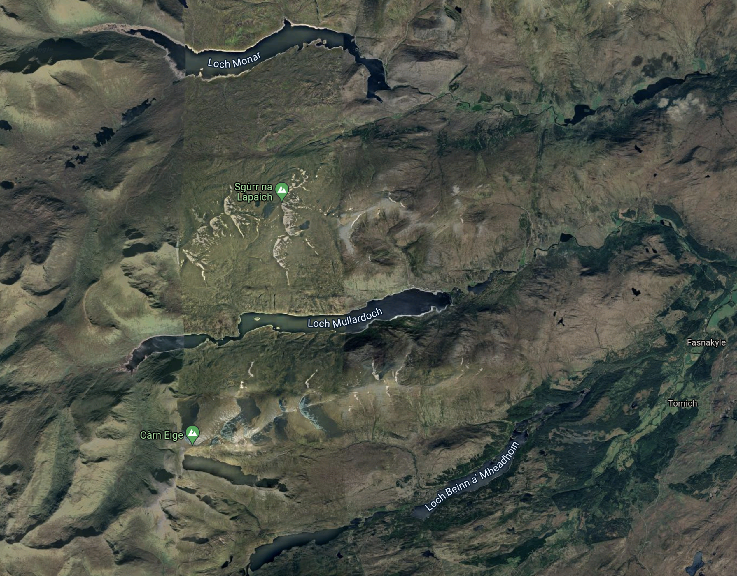
Note.
- The three lochs; Monar, Mullardoch and Beinn a’ Mheadhoin can be picked out on both maps.
- Fasnakyle, where the largest of the hydro-electric power stations in the Affric/Beauly scheme, is at the Eastern edge of the map about half-way up.
- The area doesn’t seem to have a large population.
This Google Map shows the location of Fasnakyle power station in more detail.
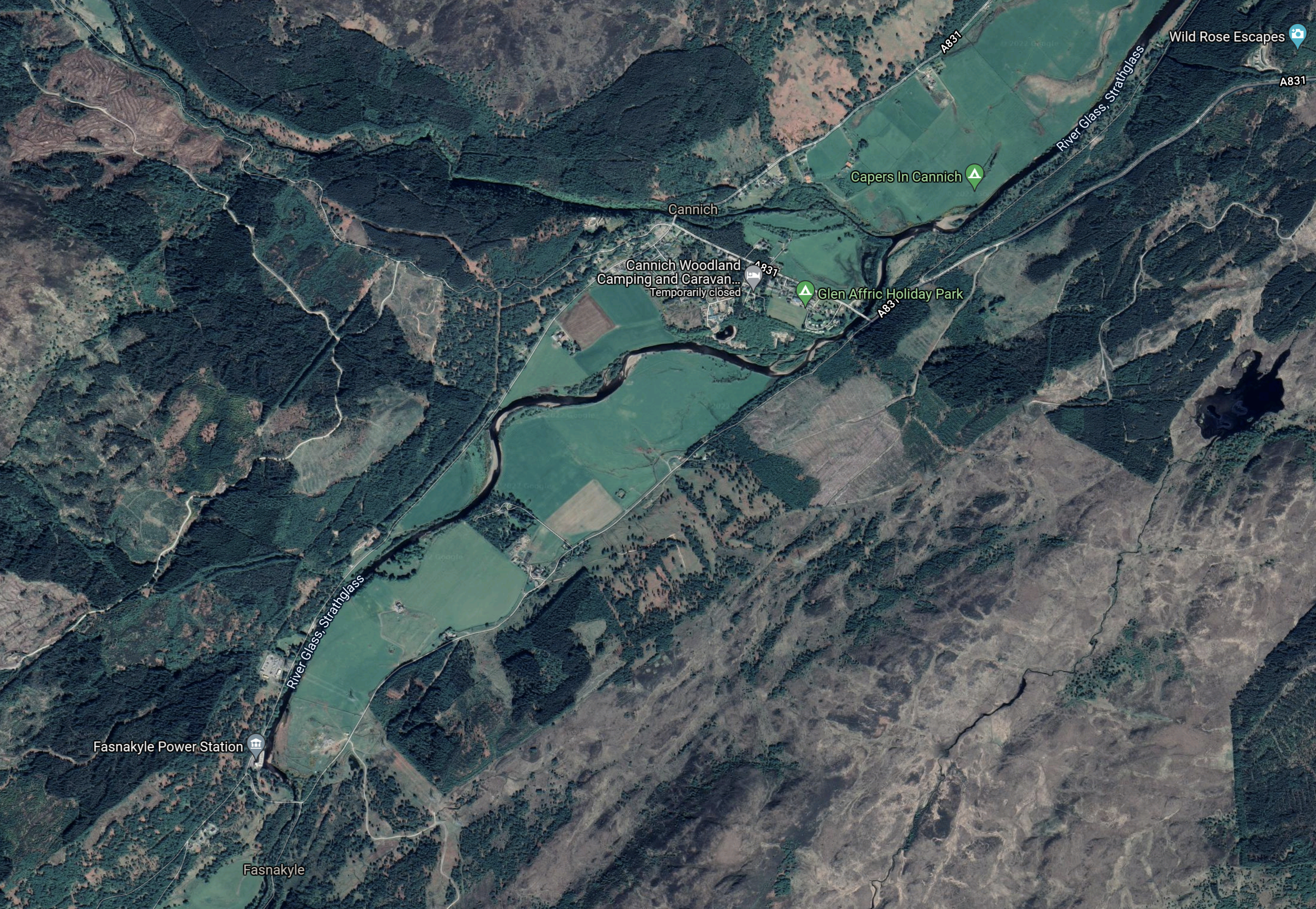
Note.
- Fasnakyle power station is in the South-West corner of the map. marked by a grey flag.
- It appears that all of the water that goes through the power station flows into the River Glass, Strathglass, which meanders its way towards Inverness on the bottom of what appears to be a broad valley.
This Google Map shows the next section of the river.
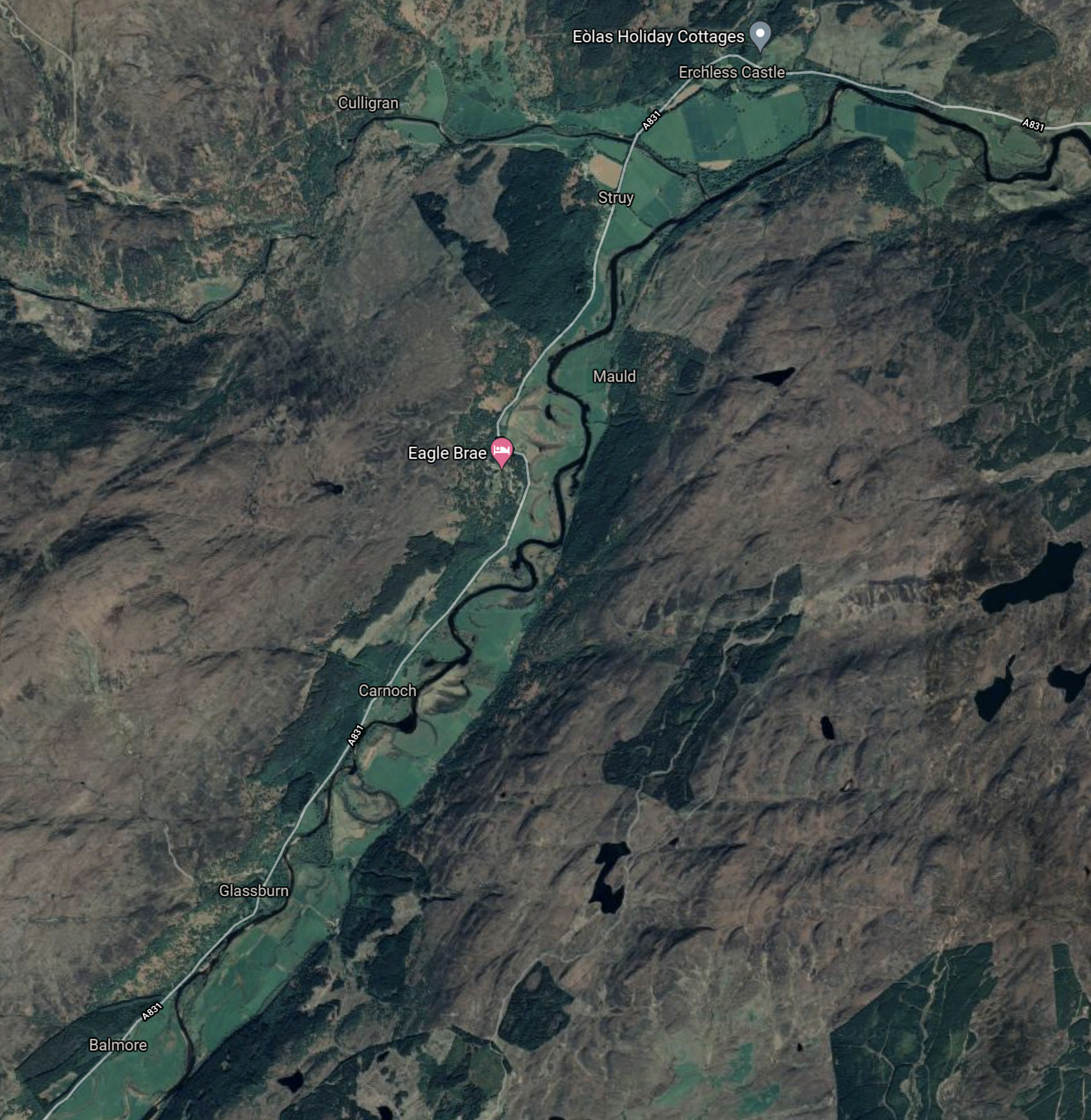
The River Glass, Strathglass joins the River Farrar near the top of the map an becomes the River Beauly.
This Google Map the River Beauly to Kilmorack.
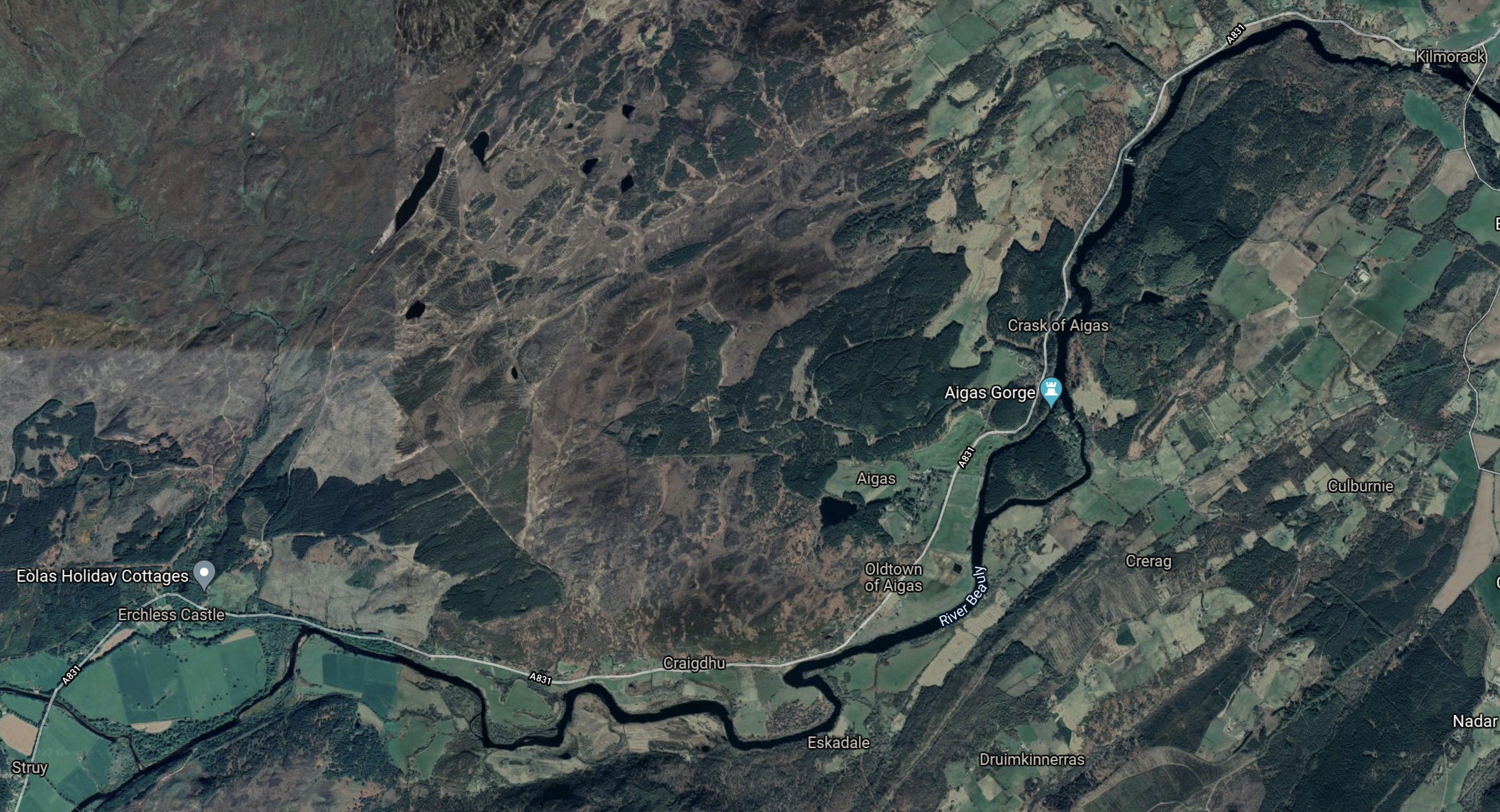
Wikipedia says this about this section of the River Beauly.
The river is part of the Affric-Beauly hydro-electric power scheme, with dams and power stations at Aigas and Kilmorack. Both have 20MW generators and include fish ladders to allow salmon to pass, the Aigas fish ladder is open to visitors in the summer.
This last Google Map shows the Beauly Firth.
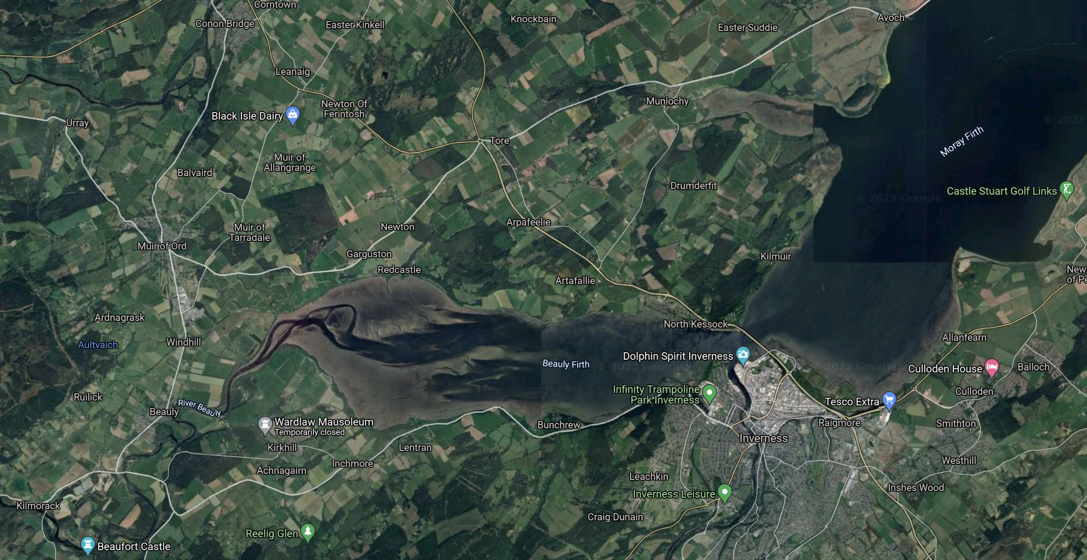
Note.
- Kilmorack is in the South-West corner of the map.
- The River Beauly flows into the Beauly Firth and ultimately out to see in the Moray Firth.
- The water flows past Inverness to the North.
It does strike me, that a lot of the water collected in the dams to the West of Fasnakyle, flows out to sea.
Strathclyde University And Pumped Storage Power For Scotland
This page on the Strathclyde University gives a list of the pumped storage potential for Scottish hydrogen-electric dams and power stations.
A figure is given for only one dam or power station in the Affric/Beauly scheme.
- Fasnakyle – 78 GWh
That would be a lot of pumped storage.
Water Flows In The Affric/Beauly Scheme
Looking at the SSE Renewables map of the Conon scheme, water flows appear to be as follows.
- Loch Monar to Loch Beannacharan via Deanie power station
- Loch Beannacharan to River Beauly via Culligran power station
- Lochs Mullardoch and Beinn a’ Mheadhoin both supply water to the Fasnakyle power station
- Fasnakyle power station to River Beauly via the River Glass, Strathglass.
- River Beauly to Beauly Firth via Aigas and Kilmorack power stations.
Note.
- Water from Loch Moray goes via Deanie , Culligran, Aigas and Kilmorack power stations on its journey to the sea.
- Water from Loch Mullardoch goes via Mullardoch , Fasnakyle, Aigas and Kilmorack power stations on its journey to the sea.
- Water from Loch Beinn a’ Mheadhoin goes via Fasnakyle, Aigas and Kilmorack power stations on its journey to the sea.
Fasnakyle, Aigas and Kilmorack power stations must work very hard.
Refurbishing And Repurposing The Affric/Beauly Scheme
Perhaps as the power stations are now over fifty years old, one simple way to increase the generating capacity of the Affric/Beauly scheme might be to selectively replace the turbines, with modern turbines, that can generate electricity more efficiently.
I suspect that SSE Renewables have an ongoing program of improvements and replacements for all of their hydro-electric stations in Scotland. Some turbines at Sloy power station have already been replaced with larger ones.
I also suspect that the whole scheme has a very sophisticated control system.
Consider.
- There is a need to control water levels to agreed minimum levels for the Atlantic salmon.
- Hydro-electric power stations have the ability to get to full power quickly, to cover sudden demands for more electricity.
- Electricity only needs to be generated if it can be used.
- Water might be held in Lochs Mullardoch and Beinn a’ Mheadhoin, as a reserve, as it goes through three or four power stations when it is released.
Over the years, SSE Renewables will have developed very sophisticated control philosophies.
Adding Pumped Storage To The Affric/Beauly Scheme
To do this a source of fresh-water must be pumped into Loch Mullardoch or Beinn a’ Mheadhoin, when there is a surplus of electricity.
It looks from Google Maps, that the river system between Fasnakyle and Aigas power stations has been effectively turned into a canal.
- I wonder, if it is deep enough to contain enough water to act as the lower level reservoir of a pumped-storage system.
- The higher level reservoir would be Loch Mullardoch.
- There would be a height difference of 200 metres.
- Calculations show around 1850 cubic metres of water would need to be pumped into Loch Mullardoch to store one MWh.
So long as enough water is left for the salmon, I suspect that if a way of pumping water from the River Glass to Loch Mullardoch, that an amount of pumped-storage can be added.
Conclusion
There would appear to be only one scheme, but if it was built it could add over 50 GWh of pumped storage.
Repurposing The Conon Hydro-Electric Scheme
The Conon hydro-electric scheme was built in the 1950s, by the North of Scotland Hydroelectric Board.
- The scheme is now owned by SSE Renewables and has a page on their web site.
- There are six individual power stations; Achanalt, Grudie Bridge, Mossford, Luichart, Orrin and Torr Achilty.
- There are six dams; Glascarnoch, Vaich, Luichart, Meig, Torr Achilty and Orrin.
This map from the SSE Renewables web site shows the layout of the dams and power stations.
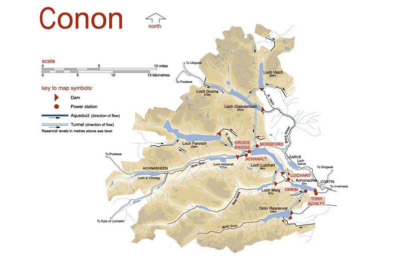
The sizes of the power stations in the scheme are as follows.
- Achanalt – 3 MW
- Grudie Bridge – 18.6 MW
- Mossford – 18.6 MW
- Luichart – 34 MW
- Orrin – 18 MW
- Torr Achilty – 15 MW
This gives a total power of 107.2 MW.
This Google Map shows the same area as the SSE Renewables Map.
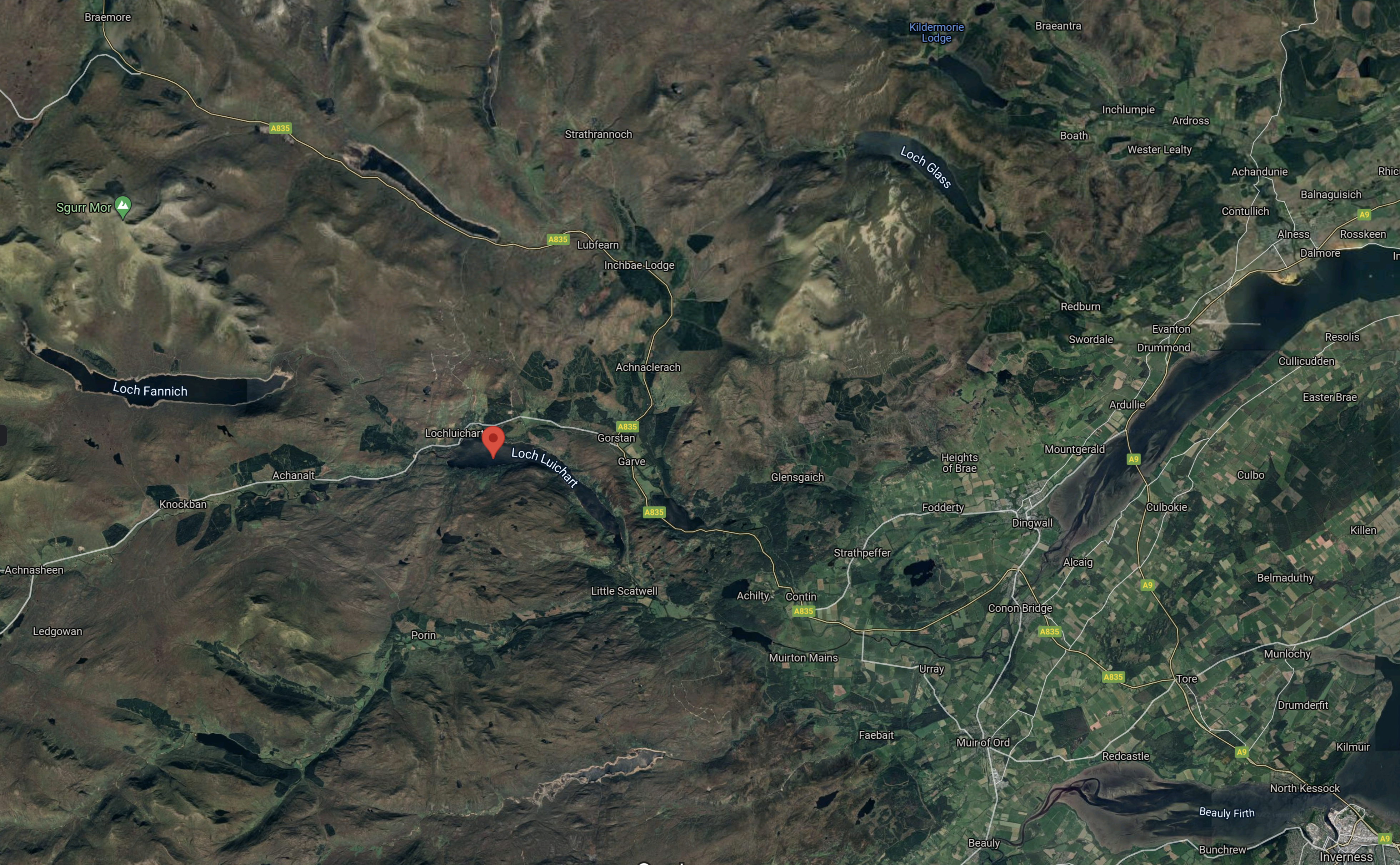
Note.
- Inverness is in the South-East corner of the map.
- The red arrow indicates the Western end of Loch Luichart.
- Loch Fannich is the large loch to the West of Loch Luichart.
- Loch Glascarnoch is the East-West loch to the North of Loch Luichart
- Loch Vaich is the North-South loch to the North of Loch Glascarnoch.
Is Inverness a City substantially powered by renewables?
Strathclyde University And Pumped Storage Power For Scotland
This page on the Strathclyde University gives a list of the pumped storage potential for Scottish hydrogen-electric dams and power stations.
These figures are given for the dams and lochs in the Conon scheme.
- Glascarnoch – 23 GWh
- Luichart – 38 GWh
- Fannich – 70 GWh
It would appear that based on research from Strathclyde University, that the Conon scheme could support up to 131 GWh of pumped storage.
This Google Map shows the three lochs and Loch Vaich.
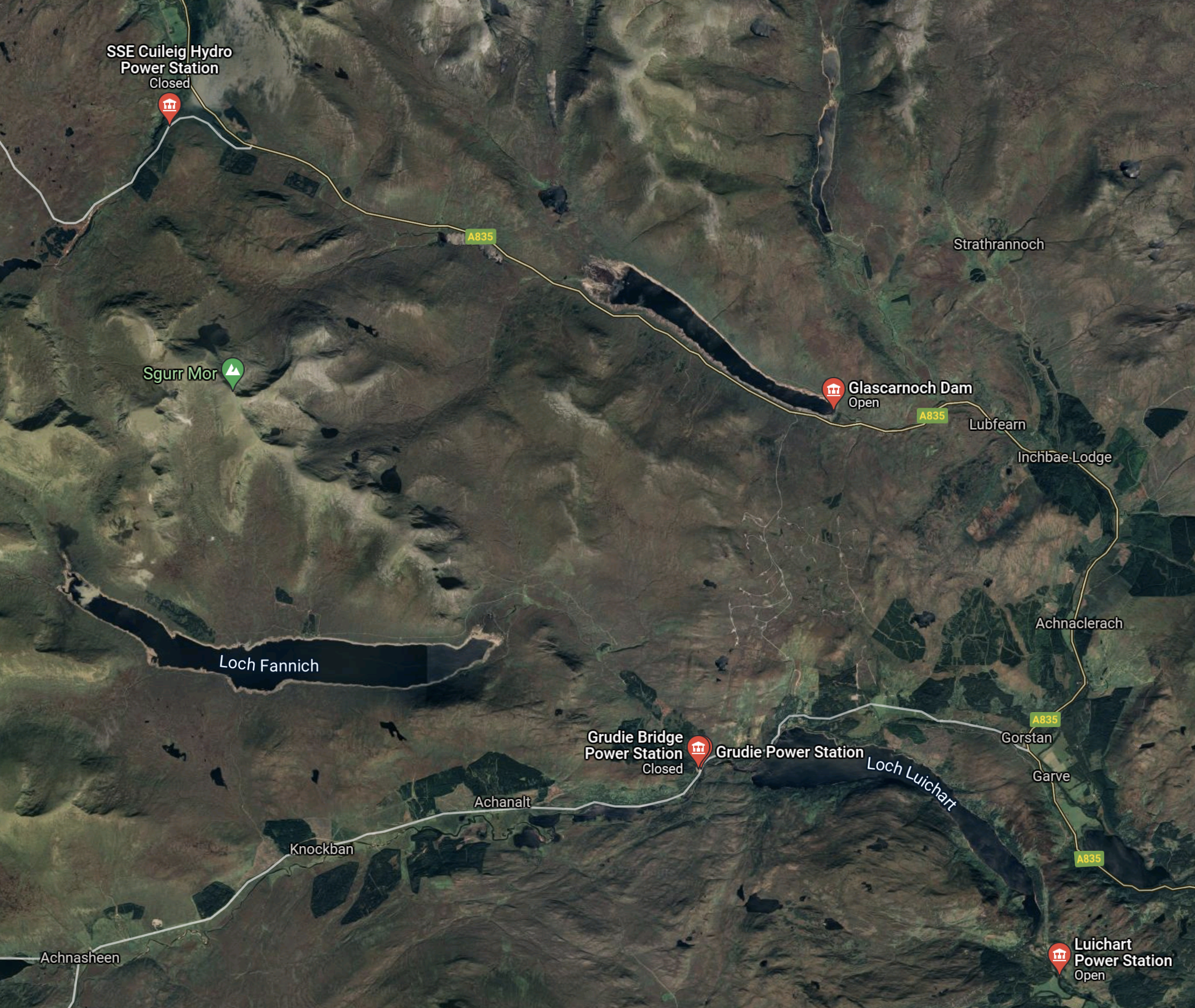
Note.
- Lochs Fannich and Luichart are named.
- Loch Glascarnoch is the East-West loch to the North of Loch Luichart
- Loch Vaich is the North-South loch to the North of Loch Glascarnoch.
- The locations of several power stations are shown.
- Cuileig is a 3.2 MW power station built in 2002.
This Google Map shows Loch Fannich.
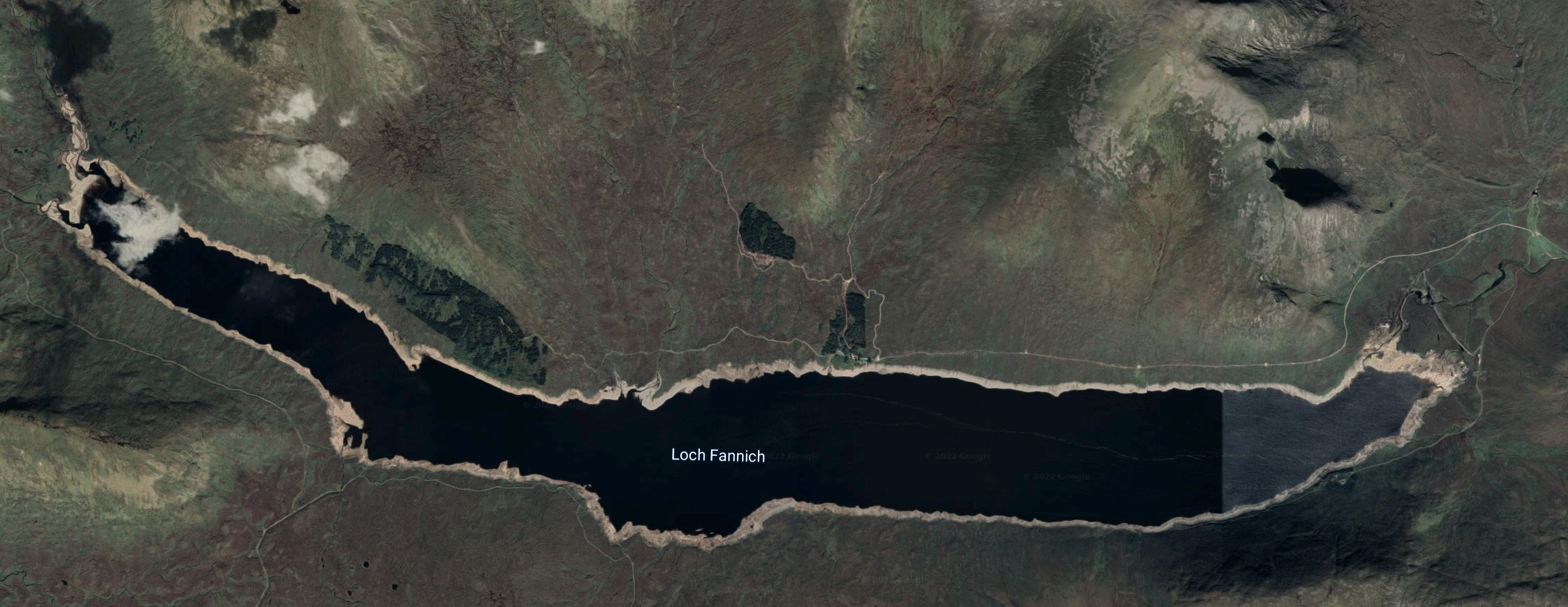
Wikipedia says this about the loch.
Loch Fannich was dammed and its water level raised as part of the Conon Hydro-Electric Power Scheme, built by the North of Scotland Hydro-Electric Board between 1946 and 1961. An underground water tunnel leading from Loch Fannich to the Grudie Bridge Power Station required blasting out a final mass of rock beneath the loch, a procedure which was referred to popularly as “Operation Bathplug”.
The dam appears to be at the Eastern end of the loch, as this Google Map shows.
I wouldn’t be surprised to find that to obtain the potential 70 GWh of storage, that the dam will need to be raised.
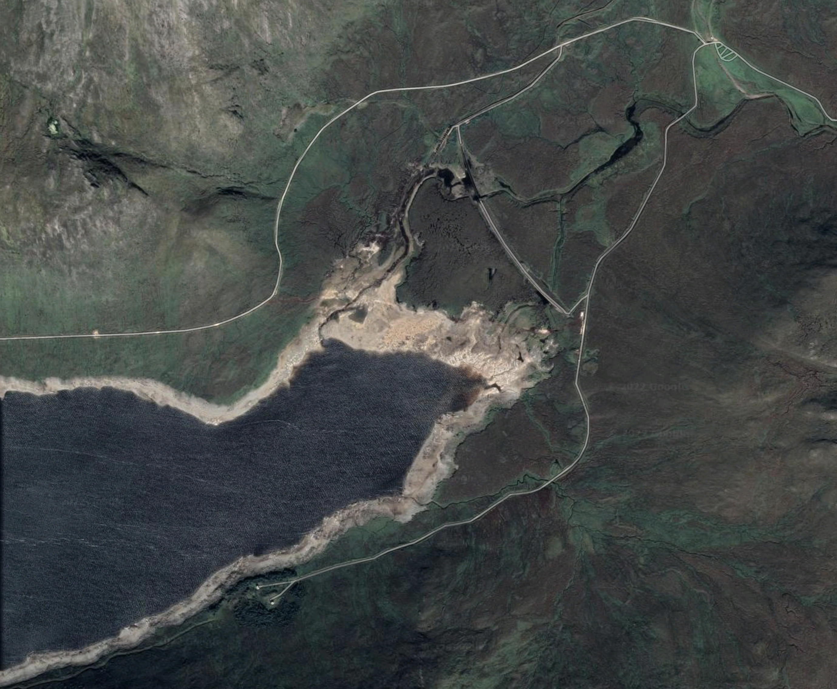
This Google Map shows Loch Glascarnoch.
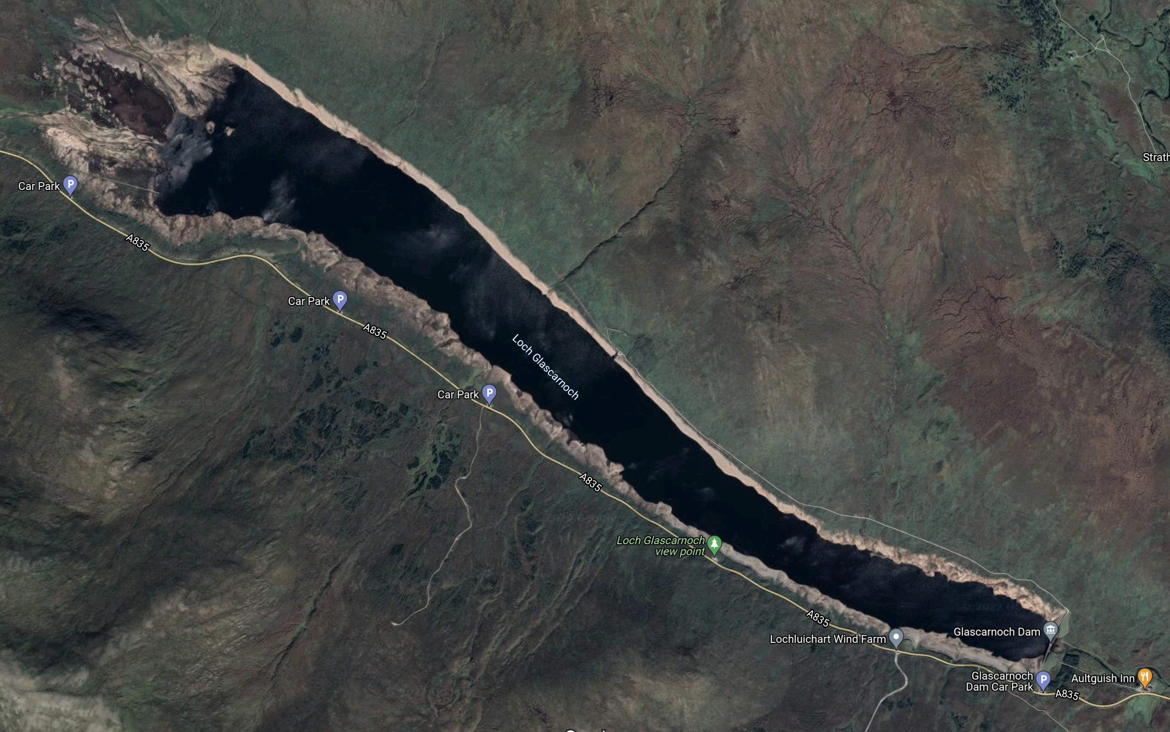
Loch Glascarnoch may be more difficult to expand, as a road runs along the Southern side of the loch.
This Google Map shows Loch Luichart
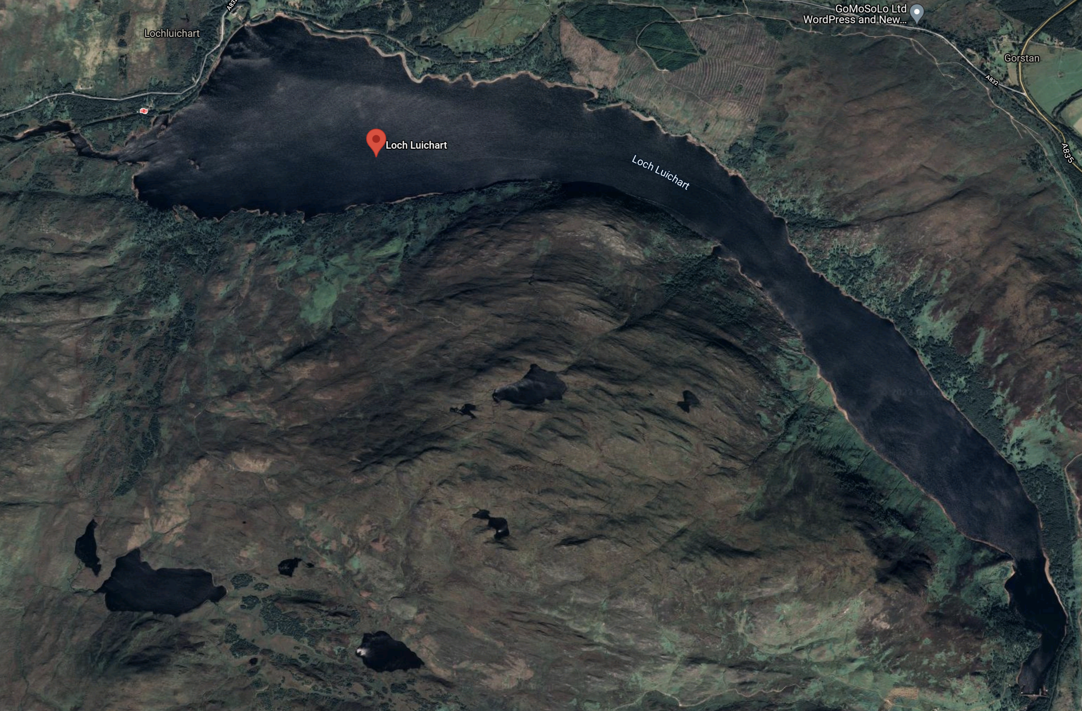
Lock Luichart may have possibilities as it is wide and could be deep.
But it will all be about the shape of the loch and the mathematics of the water.
Water Flows In The Conon Scheme
Looking at the SSE Renewables map of the Conon scheme, water flows appear to be as follows.
- Loch Vaich to Loch Glascornoch
- Loch Droma to Loch Glascornoch
- Loch Glascornoch to Loch Luichart via Mossford power station
- Loch Fannich to Loch Luichart via Grudie Bridge power station
- Loch Achanalt to Loch Luichart via Anchanalt power station
- Loch Meig to Loch Luichart
- Loch Luichart to Loch Achonachie via Luichart power station
- Orrin Reservoir to Loch Achonachie via Orrin power station
- Loch Achonachie to River Conon and eventually the Cromarty Firth via Torr Achilty power station
Note that all the power stations date from the 1950s.
Repurposing The Conon Scheme
Perhaps as the power stations are now over sixty years old, one simpler way to both increase the generating capacity of the Conon scheme and add a degree of pumped storage might be to selectively replace the turbines, with modern pump/turbines, that can both generate electricity and pump the water back up into the mountains.
It should also be noted that Loch Vaich, Loch Glascornoch, Loch Fannich and the Orrin Reservoir are all about 250 metres above sea level, with the others as follows.
- Loch Achanalt – 111 metres
- Loch Luichart – 56 metres
- Loch Meig – 87 metres
- Loch Achonachie – 30 metres
Loch Droma is the highest loch at 270 metres.
These height differences could create opportunities to put in extra tunnels and power or pumping stations between the various levels.
As water pumped to a greater height has a higher potential energy, perhaps it would be an idea to give Loch Droma, which is the highest loch, a bigger role.
Conclusion
I believe these improvements are possible.
- Adding a pumped storage facility to the Conon hydro-electric scheme, with a capacity of upwards of 30-40 GWh.
- Increasing the generating capacity by replacing the elderly turbines.
- Improving control of the scheme, by replacing 1950s control systems.
It may even be possible to substantially improve the performance of the scheme without any expensive rock tunnelling.
A Possible Balmacaan Pumped Storage System
This article on Power Technology is entitled SSE Proposes Loch Ness Hydro Power Plant.
These are the first three paragraphs.
Scottish and Southern Energy (SSE) has begun consultations to develop a 600MW hydro electric power plant on the shores of Loch Ness in Scotland.
SSE proposes to build a pumped storage scheme on the Balmacaan Estate between Invermoriston and Drumnadrochit.
The plan also includes construction of a dam and a new reservoir at Loch nam Breac Dearga, north-east of Invermoriston, according to Inverness-courier.co.uk.
This Google Map shows the location of Loch nam Breac Darga.
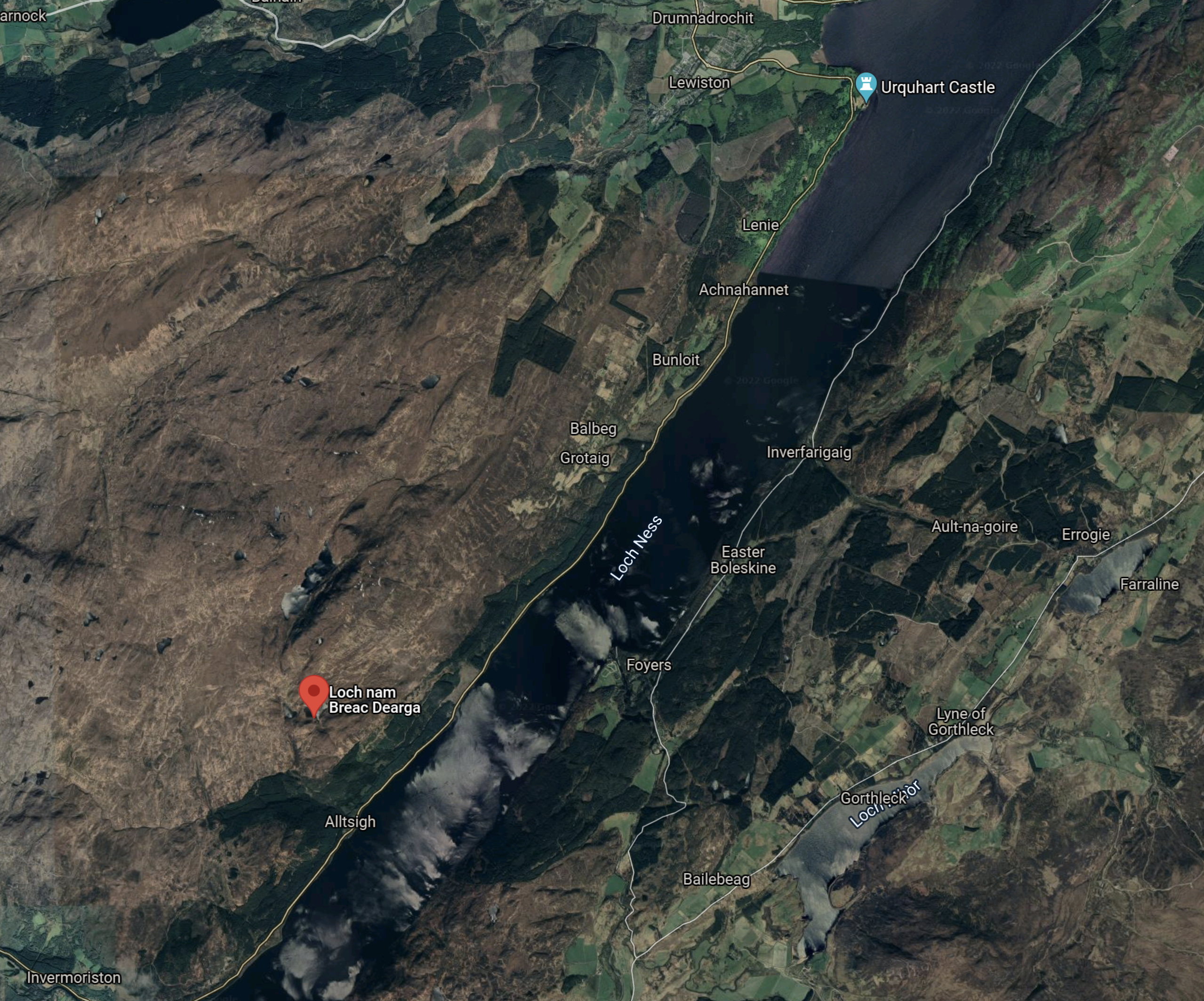
Note.
- Loch Ness runs diagonally across the map.
- Invermoriston is in the South-West corner of the map.
- Loch nam Breac Darga is marked by the red arrow and is 452 metres above sea level.
- Drumnadrochit is at the North of the map, just to the West of Urquhart Castle.
- The Foyers Pumped Hydro scheme, which I wrote about in The Development Of The Foyers Pumped Storage Scheme is on the opposite bank of Loch Ness from Loch nam Breac Darga.
This could be Scotland’s largest hydro-electric plant.
I can’t find a value for the amount of energy that can be stored, but I suspect it could be in the order of 15-20 GWh.
The stories about this project seem to be thin on the ground, so could it be that this project has been placed on the back burner by SSE.
Up To 24GW Of Long Duration Storage Needed For 2035 Net Zero Electricity System – Aurora
The title of this post, is the same as that of this article on Current News.
This the first three paragraphs.
Deploying large quantities of long duration electricity storage (LDES) could reduce system costs and reliance on gas, but greater policy support is needed to enable this, Aurora Energy Research has found.
In a new report, Aurora detailed how up to 24GW of LDES – defined as that with a duration of four hours or above – could be needed to effectively manage the intermittency of renewable generation in line with goals of operating a net zero electricity system by 2035. This is equivalent to eight times the current installed capacity.
Additionally, introducing large quantities of LDES in the UK could reduce system costs by £1.13 billion a year in 2035, cutting household bills by £26 – a hot topic with energy bills on the rise as a result of high wholesale power prices.
The report also says that long duration storage could cut carbon emissions by ten million tonnes of carbon dioxide per year.
I feel strongly, that this is a target we will achieve, given that there are at least four schemes under development or proposed in Scotland.
- Balliemeanoch – 45 GWh
- Coire Glas – 30 GWh
- Corrievarkie – 14.5 GWh
- Loch Sloy – 14 GWh
- Red John – 2.8 GWh
It certainly looks like the Scots will be OK, especially as there are other sites that could be developed according to SSE and Strathclyde University.
We probably need more interconnectors as I wrote about in New Electricity ‘Superhighways’ Needed To Cope With Surge In Wind Power.
There are also smaller long duration storage systems under development, that will help the situation in the generally flatter lands of England.
One of them; ReEnergise, even managed to sneak their advert into the article.

Their high density hydro could be a good way to store 100 MWh or so in the hills of England. As they could be designed to fit into and under the landscape, I doubt their schemes would cause the controversy of other schemes.
Conclusion
I think we’ll meet the energy storage target by a wide margin.
New Electricity ‘Superhighways’ Needed To Cope With Surge In Wind Power
The title of this post, is the same as that of this article on the Telegraph.
This is the first two paragraphs.
Energy companies are pushing for the rapid approval of new electricity “superhighways” between Scotland and England amid fears that a lack of capacity will set back the country’s wind power revolution.
Businesses including SSE and Scottish Power are calling on the industry regulator Ofgem to approve a series of major new north-south power cables in a bid to ease congestion on the existing electricity network.
These points are mentioned in the article.
- Current capacity is 6 GW, which even now is not enough.
- Another 17 GW of capacity will be needed by 2033.
- Wind farms in Scotland have been switched off and replaced by gas-fired power stations because of a lack of grid capacity.
- Another 25 GW of wind farms could be built after leases were awarded last month.
Two North-South interconnectors are being planned.
Peterhead And Drax
This is being proposed by SSE and National Grid.
- It will be an undersea cable.
- It will be two cables, each with a capacity of 2 GW.
- Peterhead and Drax power station are four hundred miles apart by road and 279 miles as the seagull flies, as a lot of the route would be over the sea. So an undersea connection would appear to be sensible.
- Peterhead is on the coast, so connecting an undersea interconnector shouldn’t be too challenging or disruptive to the locals.
- Drax power station is a 4 GW power station and the largest in the UK, so it must have good grid connections.
This Google Map shows the location of Drax power station in relation to Hull, Scunthorpe and the rivers in the area.
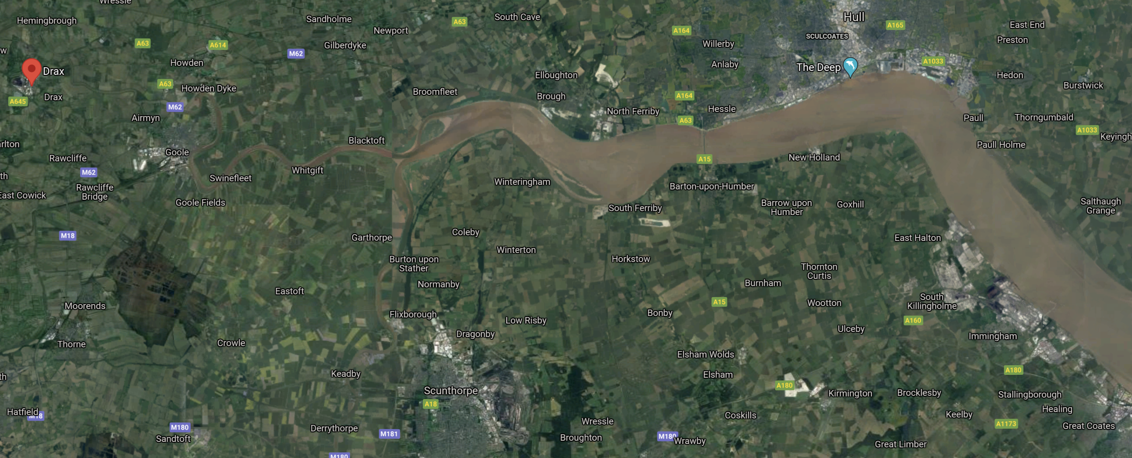
Note.
- Drax is marked by the red arrow in the West of the map.
- The large body of water in the East is the Humber Estuary.
- Hull is on the North Bank of the Humber.
- Scunthorpe, which is famous for its steel industry is South of the Humber in the middle of the map.
- To the West of Scunthorpe the Humber splits into the Trent and the Ouse.
- The Ouse leads all the way to Drax power station.
I suspect an undersea cable could go up the Humber and Ouse to Drax power station.
Is it a coincidence that both Drax power station and the proposed link to Peterhead are both around 4 GW?
Consider.
- Drax is a biomass power station, so it is not a zero carbon power station.
- Drax produces around six percent of the UK’s electricity.
- Most of the biomass comes by ship from North America.
- Protest groups regularly have protests at Drax because of its carbon emissions.
- Drax Group are experimenting with carbon capture.
- Drax is a big site and a large energy storage system could be built there.
- Wind is often criticised by opponents, saying wind is useless when the wind doesn’t blow.
- The Scots would be unlikely to send power to England, if they were short.
This is also said about Drax in Wikipedia.
Despite this intent for baseload operation, it was designed with a reasonable ability for load-following, being able to ramp up or down by 5% of full power per minute within the range of 50–100% of full power.
I take this it means it can be used to top up electricity generation to meet demand. Add in energy storage and it could be a superb load-follower.
So could the similar size of the interconnector and Drax power station be deliberate to guarantee England a 4 GW feed at all states of the wind?
I don’t think it is a coincidence.
Torness And Hawthorn Pit And Torness and South Humberside
These two cables are being proposed by Scottish Power.
- Each will be two GW.
- Torness is the site of the 1.36 GW Torness nuclear power station, which is likely to be decommissioned before 2030.
- Torness will have good grid connections and it is close to the sea.
- Hawthorn Pit is a large closed coal mine to the North of Newcastle, with a large substation close to the site. I suspect it will be an ideal place to feed power into the grid for Newcastle and it is close to the sea.
- Just South of Hawthorn Pit are the 1.32 GW Hartlepool nuclear power station, which will be decommissioned in 2024 and the landfall of the cables to the massive Dogger Bank wind farm.
- As I showed earlier with Drax, the Humber would be an ideal estuary to bring underwater power cables into the surrounding area. So perhaps the cable will go to Scunthorpe for the steelworks.
- As at Drax, there is backup in South Humberside, but here it is from the two Keadby gas-fired power stations.
The article in the Telegraph only gives the briefest of details of Scottish Power’s plans, but I suspect, that given the locations of the ends of the interconnectors, I suspect the cables will be underwater.
Conclusion
It strikes me that all three interconnectors have been well thought thought and they serve a variety of objectives.
- Bring Scottish wind power, South to England.
- Connect wind farms to the two nuclear power station sites at Hartlepool and Torness, that will close at the end of the decade.
- Allow the big 4 GW biomass-fired station at Drax to back up wind farms and step in when needed.
- Cut carbon emissions at Drax.
- Use underwater cables as much as possible to transfer the power, to avoid the disruption of digging in underground cables.
It looks to be a good plan.
SSE Renewables Launches 1.5GW Coire Glas Construction Tender
The title of this post, is the same as that of this article on renews.biz.
These are the first two paragraphs.
Hydro construction companies have been invited to submit tenders for construction of SSE Renewables’ proposed 1500MW pumped hydro storage scheme at Coire Glas, in Scotland.
Coire Glas, on the shores of Loch Lochy near Invergarry, would be the first large-scale pumped hydro storage scheme to be built in the United Kingdom for more than 30 years.
There appears to be global interest and six shortlisted bidders.
- The ANDRITZ HYDRO and Voith Hydro partnership
- The Bechtel, Acciona Construcción and Webuild S.p.A consortium
- The BAM Nuttall, Eiffage Génie Civil and Marti Tunnel consortium
- The Dragados and BeMo Tunnelling UK consortium
- GE Hydro France
- STRABAG UK
Bidders like these probably wouldn’t bother to get involved unless they knew that funding of the project was in place and it was pretty certain that the project will be constructed.
In World’s Largest Wind Farm Attracts Huge Backing From Insurance Giant, I talk about how Aviva are funding the Hornsea wind farm.
I believe, that insurance and pension companies like abrdn, Aviva and L & G could find a way of financing a scheme like Coire Glas.
Conclusion
It looks to me, that it’s almost certain that Scotland will get a 1.5GW/30 GWh pumped-storage system at Coire Glas.
Coire Glas could supply slightly more power than Sizewell B nuclear power station for twenty hours.
Now that’s what I call backup!
