Will Greater Anglia Fit Batteries To Their Class 755 Trains?
Greater Anglia have ordered the following Class 755 trains.
- 14 x three-car trains with two diesel engines in the power-pack
- 24 x four-car trains with four diesel engines in the power-pack
The power-pack would appear to have four slots, each of which could take.
- A V8 16-litre Deutz diesel that can produce 478 kW and weighs 1.3 tonnes.
- A battery of about 120 kWh, which would probably weigh about 1.2 tonnes.
I estimated the battery size , by using typical battery energy densities for a battery of similar weight to the diesel engine.
The KeolisAmey Wales Tri-Mode Flirts
The Tri-Mode Flirts ordered by KeolisAmey Wales can use either electric, diesel or battery power.
From the pictures it appears that these trains have the same basic structure as the Class 755 trains.
In the July 2018 Edition of Modern Railways, there is an article entitled KeolisAmey Wins Welsh Franchise.
This is said about the Stadler Tri-Mode Flirts on the South Wales Metro.
The units will be able to run for 40 miles between charging, thanks to their three large batteries.
So does this mean that these Flirts have just one Deutz diesel engine of 478 kW and three batteries in the four slots of the power-pack?
These trains will run between Penarth and Rhymney stations.
- I estimate about half the route will be electrified.
- Penarth to the electrification at Cardiff is under ten miles.
- The trains will work on battery power from Ystrad Mynach to Rhymney, which is ten miles up the hill.
- Coming down from Rhymney, Newton’s friend will give assistance.
This seems a challenging task, but it must be possible, even after an important rugby match in Cardiff.
I think it is true to say, that these Tri-Mode Flirts are no wimps.
Greater Anglia’s Flirts And Batteries
Four-Car Flirts
The four-car Class 755 trains don’t have a spare slot, as they have four engines.
I also suspect the four-car trains will tend to serve the longer routes or those with more passengers.
- Colchester and Peterborough
- Stansted Airport and Norwich
- Ipswich and Cambridge
- Lowestoft and London via Ipswich
- Norwich and Lowestoft
- Norwich and Great Yarmouth
Consider.
- These routes are partially-electrified.
- These routes don’t have challenging terrain.
- Except for Lowestoft and Great Yarmouth, all end stations are electrified.
- A short length of electrification could be installed at Lowestoft and Great Yarmouth stations.
I wonder if one of the diesel engines were to be replaced with a battery, by capturing and reusing the regenerative braking energy, this could improve the economics of running the services.
In Tri-Mode Stadler Flirts, I estimated the following.
- A four-car Tri-Mode Flirt will weigh around 150 tonnes.
- I will assume 250 passengers at 90 Kg. each with all their baggage, which gives a weight of 22.5 tonnes.
- This gives a total rain weight of 172.5 tonnes.
- The train is running at 100 mph.
This gives a kinetic energy of 48 kWh.
This would mean that a single 120 kWh battery could easily handle the regenerative braking and use the energy for the following purposes.
- Hotel power, which includes the power to run passenger and train systems.
- Traction power on sections, where low noise is important.
- Traction power, if there is overhead electrification failure.
- Short movements in depots and sidings.
I think that once Stadler have got their Tri-Mode Flirts working, that replacing one diesel with a battery in four-car Class 755 trains may be a sensible decision.
Lowestoft And London Via Ipswich
When the Class 755 trains are running services, there will be four direct trains per day from Lowestoft to London via Ipswich.
I will assume the following.
- There will also be four trains in both directions.
- An hourly service operates between Lowestoft and Ipswich
- Lowestoft to Ipswich will take the current 90 minutes.
- Greater Anglia will meet their promise of Ipswich to London in 60 minutes.
- The first train currently leaves Lowestoft just after five in the morning.
- The last train currently arrives at Lowestoft just before midnight.
For one train to do four round trips between five in the morning and midnight would need a round trip of around four hours and thirty minutes, which would mean that a time of around seventy minutes is needed between Ipswich and Lowestoft.
That is extraordinarily challenging.
But I think that could be Greater Anglia’s ultimate aim.
- There must be savings of a minute or two at each of the nine stations between Ipswich and Lowestoft.
- Some trains could be limited stop.
- The current maximum speed on the East Suffolk Line is just 55 mph and could probably be increased in places.
- The 100 mph Class 755 trains are quicker and probably accelerate and stop faster, than the current 75 mph Class 150 trains.
- Trains turn at Liverpool Street in under five minutes.
If it can be done, then the four trains per day between Lowestoft and London can be run with just one train.
Would batteries help the achievement of this aim?
They might do! But they would certainly improve the electrical efficiency and cut the amount of running of the diesel engines.
Three-Car Flirts
The three-car Class 755 trains have two spare slots, as they have two engines.
I would expect that the three-car trains would be used on the shorter routes and those with less passengers.
- Colchester Town and Sudbury
- Ipswich and Felixstowe
- Norwich and Sheringham via Cromer
To my mind the first two routes stand out for battery operation.
Ipswich and Felixstowe
Consider the following about the service between Ipswich and Felixstowe stations.
- The Felixstowe Branch is just over twelve miles long.
- There is one train per hour (tph) each way.
- It takes the current trains abut 26-29 minutes to do the journey.
- Currently, one train can provide the service.
In The New Trimley Freight Loop And Trimley Station, I talk about how a 1.4 km loop is being built to allow more freight trains to use the branch.
I also feel that there could be a second path in each hour for passenger trains, which would help reliability
But it also might make it possible to run a two tph service with two trains.
I also think, that if it was felt worthwhile, that this route could be run on battery power, charging at Ipswich and possibly with a short length of electrification in Felixstowe.
The advantages would be
- Diesel-free running.
- Less noise.
- The environmentally friendly trains may attract new passengers.
As with the trains on the South Wales Metro, they’d probably have one diesel engine and three large batteries.
Knowing the bicycle-friendly contours of the centre of Ipswich and Felixstowe as I do, the trains would probably need adequate capacity for bikes.
Colchester Town And Sudbury
I am sure that this new route between Colchester Town and Sudbury stations has been designed for a battery train.
Consider.
- A direct run between Colchester Town and Sudbury would probably take 45 minutes.
- Over half the route would be electrified.
- The Gainsborough Line is just eleven miles long.
- A silent battery train would be ideal for the rural route.
A Class 755 train could leave the Great Eastern Main Line at Marks Tey with full batteries, go both ways on the branch and then return to Colchester Town using the electrification.
Norwich And Sheringham Via Cromer
At thirty miles, the Bittern Line is probably too long for running totally on batteries.
But one battery handling regenerative braking would make the train more environmentally friendly.
Conclusion
Batteries would make the Class 755 trains more economical and environmentally-friendly to run, but with the exception of the Felixstowe and Sudbury branches, I suspect that the routes are too long for pure battery power.
I do believe that Greater Anglia knew about Stadler’s concept for fitting batteries on Class 755 trains before they ordered the trains.
As this opens up possibilities for the future and the ability to be more environmentally-friendly and fiscally efficient, I suspect it was a factor in their decision to buy the trains.
.
Will The Trains On High Speed Two Have Batteries For Regenerative Braking?
Regenerative braking is being fitted to most modern trains with an electric transmission.
So the proposed trains on High Speed Two will definitely use the technique.
But what will be done with the energy generated, when a train brakes?
It won’t be turned into heat, by passing the electricity through resistors on the train roof. It’s just not efficient!
Could it be returned through the electrification system to power nearby trains?
- I think this is unlikely as you can’t always be sure there is a nearby train.
- It also makes electrification more expensive.
So I’m pretty certain, that if possible, the energy created by braking will be stored on the train in batteries.
Modern high speed trains like Siemens Velaro have lots of powered axles, as this distributes the traction and braking forces along the train.
The AVE Class 103 is a member of the Velaro family and has these characteristics, which are given by Wikipedia.
- Eight cars, of which six are powered.
- Cab car length – 25.7 metres
- Intermediate car length – 24.2 metres
- Service speed – 310 kph
- Capacity – 404 passengers
- Train weight – 425 tonnes
Can this data be used to estimate the energy of a train on High Speed Two?
I will calculate the energy for an individual car.
- I know the cab cars will be heavier, but dividing the train weight by eight should give an estimate.
- So the car weight is 53.125 tonnes.
- Each car will have fifty passengers.
- So assuming each passenger weighs 90 Kg with bags etc, this gives a passenger weight of 4.5 tonnes.
- The line speed is 400 kph.
This gives a kinetic energy for a single car of 98.8 kWh.
A Bombardier Primove 50 kWh battery, which is built to power trams and trains, has the following characteristics.
- A weight of under a tonne.
- Dimensions of under two x one x half metres.
- The height is the smallest dimension, which must help installation under the train floor or on the roof.
I conclude that the train designer won’t have any problems sourcing batteries with sufficient capacity to handle the regenerative braking, that can be fitted into the train.
I would distribute the batteries along the train.
Thoughts On The New Tube For London
This article on the BBC is entitled East Yorkshire Factory Wins £1.5bn Tube Train Deal.
This is the second paragraph.
Transport for London (TfL) said the 94 trains will be designed and built by Siemens Mobility at its planned £200m facility in Goole.
But what else do we know of the design?
In 2013, I went to an exhibition of Siemens’ early design study, which I wrote about in Siemens’ View Of The Future Of The Underground.
These are the pictures I took at the time of the mock-up in the exhibition.
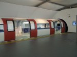
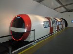
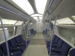
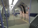
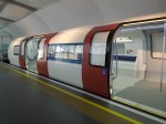
From my visit, I ascertained the following.
- The cross section appears taller and wider than the current deep-level trains.
- It has been designed so that someone of 2.6 metres can stand without stooping.
- The trains are designed to be articulated with a walk-through gangway.
- Access appears to be level between train and platform.
Will the new trains be like the mock-up?
This article on Rail Engineer is entitled London Underground Deep Tube Upgrade.
It gives some useful information and clues about the design of the New Tube for London (NTfL).
- The press release mentioned longer, walk through trains and air conditioning.
- An illustration with the press release shows all double doors.
- It is possible to provide an inter-car gangway by using an articulated configuration with more, shorter carriages.
- Bogies appear to be shared between cars.
- Bogie positioning allows all doors to be double.
- Rail Engineer’s view is that there are ten cars to a train.
- Most axles motored to deliver Victoria Line traction and braking performance.
- A 100 kph speed is quoted, as, opposed to 80 kph for current 2009 Stock on the Victoria Line.
- There might be a battery to power the train in case of power failure.
Taking all of these clues, what can I deduce?
Safe Platform Area
Before continuing, I will define what I mean as the safe platform area.
Usually on most Underground platforms without platform-edge doors, there are barriers at both ends of the platform beyond, which passengers are not allowed.
These limit the end of what I define as the safe platform area, where passengers can freely circulate and enter and leave the trains.
These pictures show the ends of various Underground platforms.
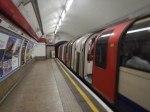
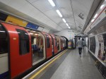
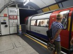
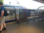
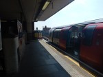
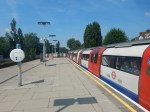


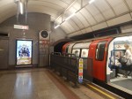


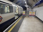

Each picture is identified with Station, Line, Direction and Train End.They all seem fairly similar.
Train Length And Car Length
The press release says the new trains will be longer.
The current length of the 1973 Stock on the Piccadilly Line is 106.8 metres.
This length is determined by the underground platforms, where if the driver stops, so that they can get off into the protected area, at the forward end of the platform, the rear end of the train is still in the tunnel.
The end passenger doors are of course in the safe area of the platform.
From looking at trains at Kings Cross station and judging it against the known length of a 1973 Stock train, I estimate that the length of the safe area is around ninety-five metres.
Looking at the picture of the cab in the mock-up, there is no driver’s door. So I will assume that drivers will access the cab from the passenger compartment. This probably means that the trains could be a little bit longer and still give access to all cars on the train.
The Rail Engineer article speculates that the trains will have ten sections of which two must have cabs on one end.
I think this will mean the following.
- There will be nine bogies between cars.
- There will be an end bogie under the cab of both driving cars.
- Each passenger car and the passenger section of the driving cars, will have two double doors on either side.
- I believe that the interiors of the passenger cars and the passenger sections of the driving cars will be virtually identical.
- The driving cab would be perhaps four metres long and could have a plant room behind it.
- The driving cab and its structure would probably incorporate a crush zone.
If the end pair of doors behind the driver’s cab, were locked out on underground platforms, this would not cause inconvenience to passengers. It certainly doesn’t now, when selective door opening is used at various stations on the Underground, like Baker Street station on the Sub-Surface Lines.
So perhaps, the safe platform area will go to the middle of the passenger compartment in the driving cars?
This will mean that.
- At some stations only one door can be used in the end cars.
- Access will always be available through the second door of the car or the two doors in the next car.
- The driver can easily access the cab, through the bulkhead door between the cab and passenger compartment.
This will also mean that there will be eight passenger cars and two half passenger sections from the driving cars in the safe platform area.
It should be noted that on the Victoria Line trains have always stopped automatically in the correct position, so this wouldn’t be difficult to arrange with automation of this function on the NTfL
Suppose the safe platform area can be stretched to 108 metres, this would mean.
- The passenger cars would be 12 metres long
- The passenger sections of the driving car would be 12 metres long.
- The driving cars would be perhaps 16 metres long.
This would give a total train length of 128 metres, with a passenger compartment that is 120 metres long.
Obviously, these lengths are speculative and others will work.
- 12.5 metre passenger cars would result in a 133 metre long train and would need a 112.5 metre safe platform area.
- 13 metre passenger cars would result in a 138 metre long train and would need a 117 metre safe platform area.
- 14 metre passenger cars would result in a 148 metre long train and would need a 126 metre safe platform area.
I do think the figures show, that if trains can overhang the safe platform area, then trains can be longer and train capacity can be increased.
It also shows, that if the safe platform area can be lengthened, so can the trains, which would further increase capacity.
But lengthening platforms, especially in tunnels can be very expensive!
Train Length On Other Lines
These trains must also fit the Bakerloo, Central, Jubilee, Northern and Waterloo & City Lines.
These lines all have different length trains.
- Bakerloo – 114 metres
- Central – 133 metres
- Jubilee – 126 metres
- Northern – 108 metres
- Waterloo & City – 66.5 metres
To further complicate matters, some stations on the Jubilee Line have platform-edge doors.
The Rail Engineer article states that the NTfLwill have ten articulated segments.
If all the passenger cars are identical, then a longer or shorter train should be able to be created by fitting an appropriate number of passenger cars between the two driving cars.
Train Length On The Waterloo & City Line
A five-car train with twelve metre segments and sixteen metre driving cars, would be 68 metres long and could fit the simple platforms of the Waterloo & City Line.
Train Capacity
The capacity of the 1973 Stock is 228 seated and 684 standing passengers.
The most modern deep tube trains on the Underground are the 2009 Stock of the Victoria Line.
These trains accommodate 252 seating and 1196 standing passengers in a train length of 133.3 metres, which is 10.85 passengers per metre.
A better comparison might be the S7 Stock of the Circle Line, as they have similar a seating arrangement to the NTfL.
These trains accommodate 865 sitting and standing passengers in a length of 117.5 metres, which is 7.36 passengers per metre
As the passenger section of the proposed design for the NTfL is 120 metres,
- This gives a capacity .of 1302 passengers using the 2009 Stock figure.
- This gives a capacity .of 883 passengers using the S7 Stock figure.
The actual figure is probably somewhere in the middle. I shall use 1100, which is an increase of twenty percent over the current trains.
Train Weight
Obviously, I don’t have the weight of the proposed NTfL.
A 2009 Stock train weighs 197.3 tonnes and is 133.3 metres long.
My guess for the length of a proposed NTfL is 128 metres.
The best I can come up with is to say that the NTfL is the same weight per metre as the 2009 Stock.
This gives the weight of the NTfL as 189.5 tonnes.
I would put an error of 25 tonnes on that figure either way.
Train Kinetic Energy
The value of the kinetic energy of the train is important, as it determines the energy that must be.
- Transferred to the train to accelerate it up to speed.
- Absorbed by the braking system, when the train stops.
Consider.
- The basic train weight is 189.5 tonnes.
- There are 1100 passengers.
- With bags, buggies and other things passengers bring on, let’s assume an average passenger weight of 90 kg, this gives an extra 99 tonnes.
- This gives a total train weight of 288.5 tonnes
If the train is travelling at 100 kph, this gives a kinetic energy of 30.9 kWh.
Regenerative Braking
The S Stock trains of the sub-surface lines have regenerative braking.
This saves energy and it will certainly be applied on the proposed NTfL.
The regenerative energy system on the S Stock returns the electricity through the electrification to power other trains nearby. This means a braking train effectively powers one that is accelerating.
The Rail Engineer article about the NTfL, says that most axles will be powered.
- This gives good acceleration and smooth regenerative braking.
- I would not be surprised to see a small battery of about 5 to 10 kWh in each car to handle the regenerative braking.
- When the train brakes the traction motors will pass their generated energy to the battery.
- On acceleration, the traction motors would use the energy stored in the battery.
One of the great advantages of using batteries with regenerative braking in tunnels, is that it reduces the amount of heat that a train emits into the trunnel.
Electrical System
I wouldn’t be surprised to see each car designed like a serial hybrid bus.
- The third-rail electrification and energy from regenerative braking would charge the battery.
- Each car might have its own pickup shoes.
- The battery would power the car’s traction motors and other systems.
An intelligent computer system would control each car and the whole train.
Effectively, the train could be a connected string of ten independently powered cars.
Think liberty horses with a ringmaster in charge.
Keeping The Tube Cool
This article on IanVisits is entitled Cooling The Tube – Engineering Heat Out Of The Underground.
Read it and you’ll find all the methods Transport for London are employing to make Underground travel better.
The first thing that must be done is to make sure that the proposed NTfL do not increase the heat input into the tunnels and trains to make the experience hotter
The train must be well-insulated, so that if the temperature in the train is at the required level for passengers, it tends to stay there and only change slowly.
The second thing that must be done is that the train should be designed so that it puts a minimum level of heat into the tunnels.
- Regenerative braking to batteries will help, as it will mean that braking should be heat-free and the train will be taking less traction current from the rails.
- An aerodynamic train will produce less heat from friction.
- Traction motors and other electrical systems will produce heat.
I suspect Siemens will look at every component of the train and heat production will be one of the criteria.
I also believe that the design of an intelligent air-conditioning system is important.
Suppose you are trying to use air-conditioning to cool a 30 °C train in a 30 °C tunnel. All you’ll do is heat the tunnel even more.
Take the Piccadilly, Jubilee and Central Lines, which all have surface sections at both ends.
So why not cool the trains on the surface to say 22 °C, before they enter the central tunnels?
- There will be no problem venting the heat to air.
- The outside air temperature on the surface, will probably be less than in the tunnels
- If the trains are well-insulated, this will help.
By the time the trains get to the other end of the tunnel, the train’s temperature will have risen and then the cycle is ready to start again.
Some trains spend thirty minutes or more running on the surface in a round trip of more than an hour.
Emergency Train Recovery Using Battery Power
If there is sufficient battery capacity, then this must be possible.
Conclusion
These trains could be very different than the trains they replace.
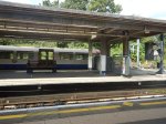
Surprising Electrification At Oxenholme
I took these pictures of the Windermere platform, which is numbered 3, at Oxenholme station on the 7th May 2018.

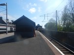
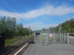

Note the overhead wires for electric trains.
This picture is from an earlier post dated the 1st May 2015.
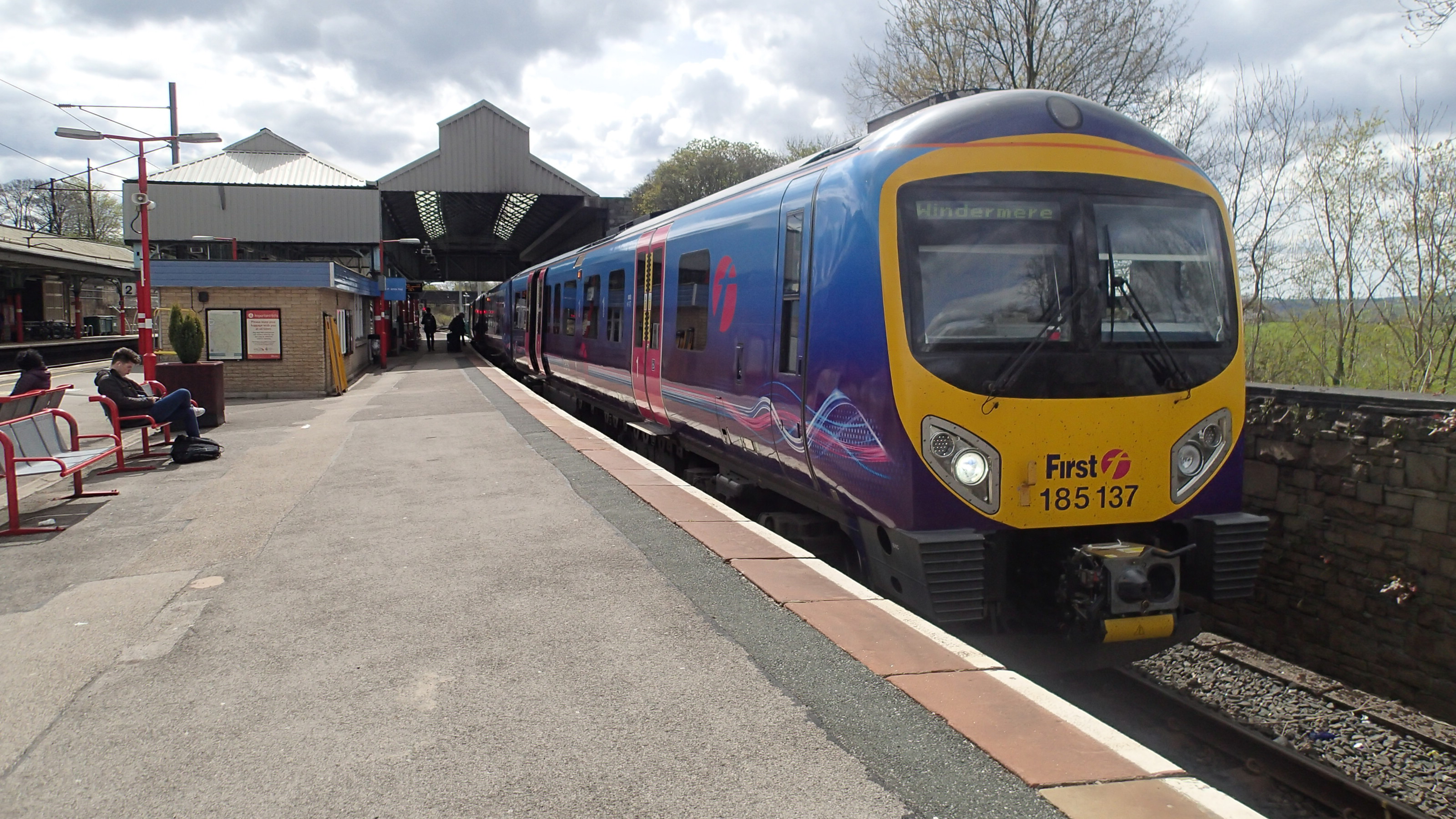
There are no overhead wires in the picture.
In the Electrification Proposal section of the Wikipedia entry for the Windermere Branch Line, this is said.
On 20 July 2017, it was announced that electrification of the Windermere branch was cancelled. As an alternative, Northern plan to utilise Class 769 multiple units on the route; these are Class 319 electric multiple units converted to function as bi-mode units, capable of operating under electric power between Manchester and Oxenholme, and under diesel power on the Windermere branch.
Did Grayling’s announcement come too late to stop these wires being erected?
This Google Map shows the station.
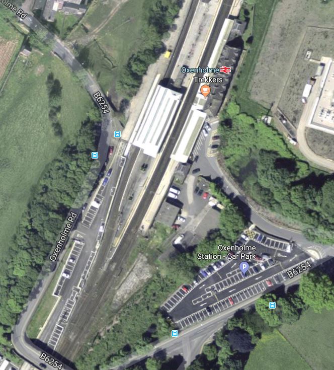
Note how Platform 3 is accessible from the South. North of the station, Platform 3 only leads to the Windermere Branch Line.
Bi-Mode Trains
The short length of additional electrification would be ideal for a bi-mode train, like the Class 769 train, which will be working the line in the near future.
Going towards Windermere, the train would arrive in Platform 3 having used electrical power at speeds of up to 100 mph from Manchester Airport. The pantograph would be lowered and the train would move on to Windermere using diesel power.
Coming from Windermere, the train would change from diesel to electric power in Platform 3.
It is a very conservative method of changing power source, to do it in a station, as if anything goes wrong, the passengers are only stranded in a station, rather than in the middle of nowhere.
In their previous incarnation as dual-voltage Class 319 trains, the voltage changeover was always done in Farringdon station.
Battery Trains
The Windermere Branch Line is ten miles long, so out and back from Oxhenholme should be well within range of a battery electric multiple unit, if not now, in a couple of years time.
A battery electric multiple unit, perhaps developed from Bombardier’s Class 379-based BEMU demonstrator, would be ideal for the Windermere to Manchester Airport service.
- The Class 379 trains were built in 2010-2011, for the Stansted Airport service.
- They will be released by Greater Anglia in 2019.
- They are 100 mph trains.
And then there’s the Class 230 train!
These trains would do a good job running an hourly shuttle between Oxenholme and Windermere, but they could be unsuitable for long-term use.
- The capacity would be too low.
- They are too slow to run on the West Coast Main Line.
- Running a service between Windermere and Manchester Airport might be too far.
But undoubtedly, a well-designed battery train would be able to work the Windermere Branch Line.
- Services between Windermere and Manchester Airport would charge batteries on the electrified lines.
- Batteries could be topped up as required in Oxenholm station.
- There would be no need to electrify the Windermere Branch Line.
Wordsworth would have written a poem about battery trains gliding quietly through the Lake District.
Conclusion
Network Rail have future-proofed the electrification at Oxenholm station in a very professional way.
Has The Queen Ever Ridden In a Battery-Powered Train?
Countryfile this evening had a special program about the Queen’s Scottish house and estate at Balmoral.
One archive film, showed her arriving at Ballater station in a train hauled by a locomotive with a number that looked slightly familiar. Looking it up, it was a B1 Class locomotive, which I must have seen regularly, when I went train-spotting on the West Anglia Main Line in the 1950s.
So I looked up Ballater station in Wikipedia.
The station, which was on the 43 mile long Deeside Railway from Aberdeen, is now closed but there was this paragraph on Wikipedia under Services.
When the battery multiple unit was introduced, services were doubled to six trains a day from 21 April 1958, and Sunday service reinstated. The line was chosen for testing the unit because the stations were well spaced and the 1 in 70 ruling gradients would require substantial discharge rates.
As someone very interested in railways at the time, I’d never heard of British Rail’s use of battery trains.
Remarkably, the battery electric multiple train, is still in existence and is being preserved at the Royal Deeside Railway, not far from Balmoral.
It looks to me. that a lot of engineers at Derby, made sure that this train survived.
So what was it like?
- It was based on the Derby Lightweight diesel multiple unit.
- The North of Scotland Hydro-Electric Board initiated the design and was a joint sponsor.
- The train had an operating speed of 60 mph.
- The train was powered by two 100 kW traction motors.
- Power was provided by 416 lead-acid cells, giving a total of 440 V and 1070 A hour capacity.
- The batteries weighed nine tonnes.
- There were seats for twelve First Class passengers and a hundred and five in Second Class.
It couldn’t been that bad a train, as it ran between Aberdeen and Ballater station from 1958 to 1962.
There’s more about the train here.
Conclusion
But I can’t help wondering, if the Queen ever used the train!
Discontinuous Electrification For Valley Lines?
The title of this post, is the same as that of an article in the May 2018 Edition of Modern Railways.
The Valley Lines in question are the Cardiff Valley Lines, that fan out from Cardiff Central and Cardiff Queen Street stations in various directions.
- Some of the lines into the valleys are quite steep.
- The lines in the Cardiff area seem to be typical coastal lines and fairly flat.
- The lines are a mixture of single and double track.
- There are various plans to extend some of the branches.
According to the article, it would appear that the current diesel system would be replaced with a system, with these characteristics.
- Light rail vehicles
- Discontinuous electrification
- Use of stored energy.
- Street running is expected to be in the specification for the vehicles to be used, to allow extension in the Cardiff Bay area and perhaps other places.
The proposal would save costs against full electrification and heavy rail.
My observations follow.
Batteries
Batteries will be an integral part of the design of the new rail vehicles.
Powering The Trains
The article states that battery power will be used to power the trains on sections that are difficult to electrify, like the mile-long Caerphilly Tunnel.
Battery power could also be used on level and downhill sections of track up to a few miles, but I suspect on steep uphill sections, electrification will be needed.
Handling Regenerative Braking
I believe that regenerative braking will be employed on the rail vehicles and the energy generated will be stored in the batteries.
The main advantage of this is that it simplifies the power supply to the electrification, as it only has to handle power going to the train.
This less complex electrical system, saves construction costs.
Recovering The Train’s Potential Energy
A train travelling from Cardiff to one of the terminal stations at the heads of the valleys, will need to acquire an amount of potential energy, based on the train’s mass and the height involved. This will be provided by the train’s traction system powered by the electrification and the energy in the batteries.
Coming down the hill, the regenerative braking will control the speed of the train and store any energy generated in the batteries.
This will save on the cost of energy to operate the system.
Charging The Batteries
The batteries will be charged from both the overhead electrification and the regenerative braking.
Extensive simulations of the route on computers would be able to calculate the following, for a wide range of scenarios.
- The size of the batteries.
- The power of the traction motors.
- Where the electrification needs to be installed.
- The maximum power output of the electrification system.
These calculations could also lead to an energy-saving operating philosophy, that could be programmed into the train’s computer system.
I suspect the worst case scenario, would be a train full of the heaviest Welshmen after an important rugby match at the Millennium Stadium.
Electrification
My thoughts on how various sections of track would be electrified follow.
Tracks With A Significant Uphill Gradient
These would need to be electrified, as I doubt battery power on the steepest gradients, would be enough to take a fully-loaded train to the top of the hill.
Electrification would be lighter-weight 750 VDC overhead wires.
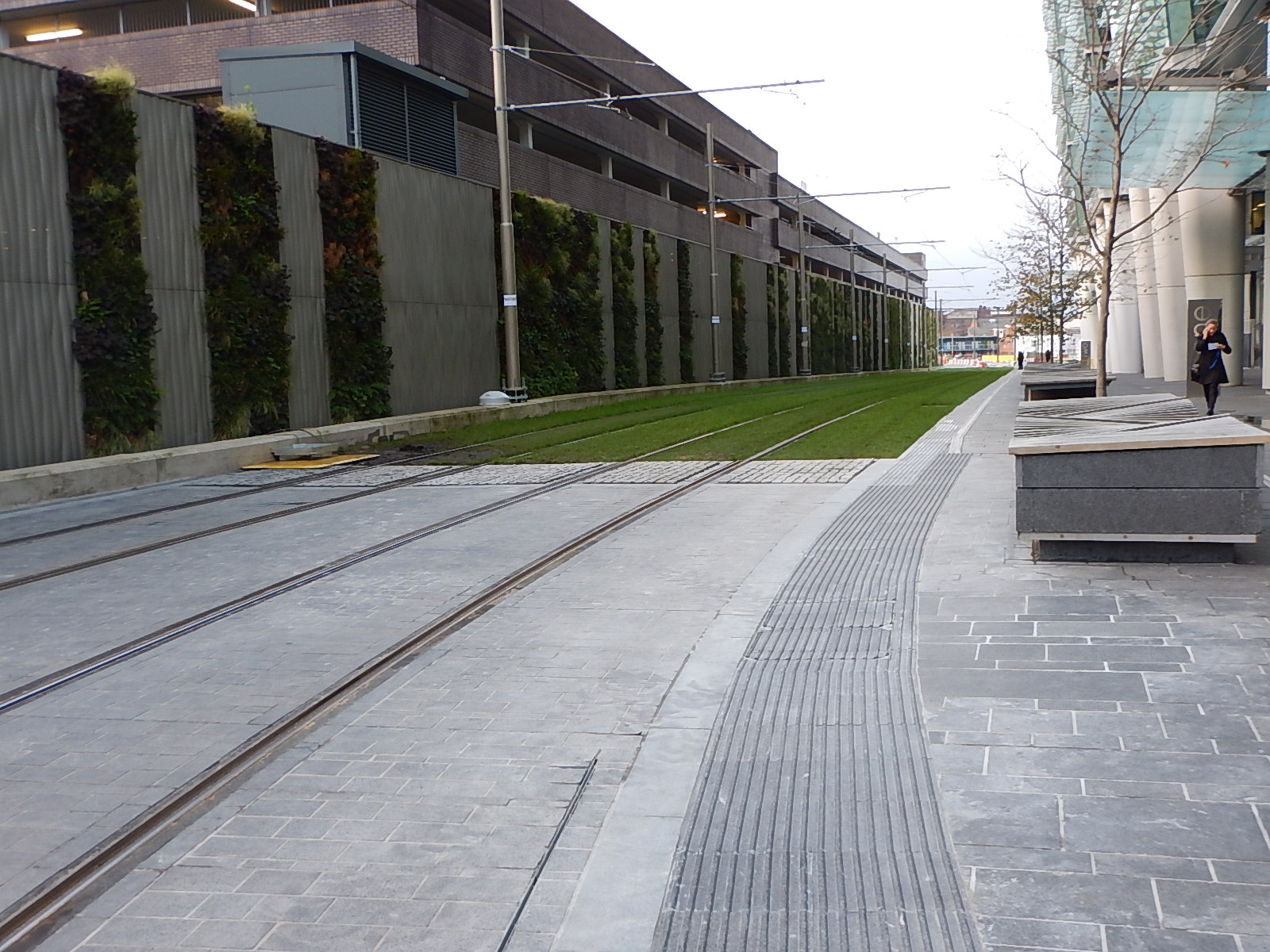
The picture shows some of the overhead wires in Birmingham, that are used by the Midland Metro’s Urbos 3 trams.
Tracks With A Downhill Gradient
These would not need to be electrified, as Newton’s friend gravity would do most of the work.
However, as batteries will be fitted, these can have three important functions on downhill stretches of track.
- Give the tram a nudge if needed.
- Restart the train after a stop at a station.
- Store any energy created by regenerative braking.
Note that we could have the unusual situation on a double-track section of line, where the uphill track was electrified and the downhill track was left without electrification.
Level Tracks
These would not need to be electrified, as battery power would be used to propel the train.
Selected Stations
Some stations could need to be electrified to ensure that the service was reliable. These might include terminal stations or those with tricky gradients on either side.
Tracks With 25 KVAC Electrification
Some of the tracks used by the trains on the Cardiff Valley Lines should be electrified with 25 KVAC, by the end of December 2018.
Class 399 tram-trains, that are used in Sheffield can use either 750 VDC and 25 KVAC overhead electrification.
it would probably be a good idea, if the new vehicles on the Cardiff Valley Lines could also use both voltages.
Automatic Pantographs
The pantographs on the vehicles would be raised and lowered automatically to access the electrification. This could even be GPS-controlled and able to be carried out at line speed.
Tram-Trains?
I very much feel, that tram-trains could be used to advantage.
- Some of the Valley Lines are also used by freight trains, so couldn’t be converted to trams-only.
- Tram-trains like the Class 399 tram-train, under test in Sheffield can work on both 750 VDC and 25 KVAC overhead wires.
- Tram-trains can use conventional railway signalling.
- Tram-trains could work on the South Wales Main Line to Newport.
- Modern tram-trains like the Class 399 tram-train have performance, that is about the same as a Class 142 train, which is a Pacer, that works the Cardiff Valley Lines, in large numbers.
- Tram-trains could run on the streets as trams, as they do in Sheffield.
Several manufacturers make tram-trains, which I believe could be suitablefor the Cardiff Valley Lines.
Stadler’s Class 399 Tram-Trains
Nothing is said about the vehicles, that would be used, but I think they need the following characteristics.
- Ability to climb the steepest section of the routes using 750 VDC overhead electrification.
- Ability to store energy.
- Regenerative braking to charge the batteries coming down the hills into Cardiff.
- A similar capacity to a Class 150 train, which is around 150 seats.
- It would be a bonus if they could use 25 KVAC overhead electrification, which will be available on part of some of the routes.
- Ability to raise and lower the pantograph quickly and automatically.
- Ability to run on the National Rail network.
- Ability to run on the street.
This specification is virtually the same as a Class 399 tram-train with the following additions.
- More seats and possibly an extra car.
- Batteries.
Class 399 tram-trains are a UK version of the Stadler Citylink tram-train. The German version is used in Karlsruhe to climb into the hills surrounding the city, on routes that are as challenging as the Cardiff Valley Lines.
So I have no worries about a version of the Class 399 train handling the Cardiff Valley Lines.
I certainly believe after my experience in Karlsruhe, and looking at other Citylink variants, that Stadler can come up with a tram-train for Cardiff based on the Class 399 tram-train.
And Then There’s CAF!
CAF have provided the Urbos 3 trams for Edinburgh Trams and the Midland Metro.
These are modern trams, that will be doing the following in a few years in the Midlands.
- Running on stored energy in the centre of Birmingham and to Wolverhampton station.
- Sharing the South Staffordshire Line with heavy freight on a new route to Merry Hill Shopping Centre.
This sounds like a tram-train with stored energy.
Wikipedia also lists a version of the Urbos family, called an Urbos TT, which is described like this.
The Urbos TT series is built with tram-train technology, connecting existing heavy rail infrastructure directly to urban tramway systems.
This document on the CAF web site, gives more details of Urbos variants, including the Urbos TT.
Looking at the modular nature of the design, you could have a custom-built tram-train tailored to the rail network.
But surely, the major factor with CAF, is that they have recently opened a factory at Newport.
If CAF get the order for the Cardiff Valley Lines, they could do a substantial part of the train building in a factory connected directly to the lines.
Converting The Valley Lines
I think that there are advantages and cost savings to be had, by good design in this area.
Could The Rail Vehicles Be Designed To Fit The Existing Platforms?
The first thing to do would be to design, build and fully test the rail vehicles.
Could the tram-trains be built, so that they fitted all the existing platforms?
- Class 150 trains are 2.82 metres wide.
- Urbos 3 trams on the Midland Metro are 2.65 wide.
If the tram-trains could run without platform modifications, this would be a big cost saving and still allow diesel units to use the lines, at the same time.
Testing The Trains
If the tram-trains were being given a 25 KVAC capability, they could even be tested on the quadruple-track the South Wales Main Line after the line is electrified through Newport.
Electrifying The Lines
It could be that the only sections of the valley lines that will need electrification, are the steep lines into the hills, as all other sections could use stored power or the 25 KVAC, where it exists.
- It would probably be possible to put up the simpler 750 VDC overhead lines during weekend and perhaps longer possessions.
- The electrification could be designed so that it doesn’t interfere with existing services.
- The lines would be converted one at a time.
- ,Note that tram-trains could share track and platform with the current diesel trains working the lines.
If CAF were to get the order surely the Ebbw Valley Line, which could be connected easily to the factory would be the first to be converted.
Conclusion
Obviously, the devil will be in the detail, but it does look like a viable plan will emerge.
I think that if CAF get the order, that they could be big winners.
The Cardiff Valley Lines could demonstrate the following.
- Running on main lines with 25 KVAC electrification.
- Running on 750 VDC electrification.
- Running on batteries.
- Running on lines with steep hills.
- Street running.
- Sharing tracks with freight trains and other passenger services.
- The tram-trains could also connect to Cardiff Airport.
It is a world-class demonstration and test track for innovative tram-trains, designed to cope with challenging rail networks.
With a factory close by at Newport, the selling of the tram-trains to other operators would be a salesman’s dream.
I think there’s more to CAF coming to Newport, than was apparent, when the deal for the factory was signed.
Auckland Rows Back On Battery Train Plan
The title of this post is the same as this article on the International ailway Journal.
This is said.
Following approval by Auckland Council, the proposal went to the New Zealand Transport Agency (NZTA) for final sign-off. However, in the run-up to New Zealand’s general election on September 23, a political consensus emerged in favour of bringing forward electrification of the Papakura – Pukekohe line, prompting the NZTA to reject the case for battery trains.
Can we assume the reason for the change of order is political?
Certainly, CAF, who are building the trains seem to have the required battery technology. This is also said.
CAF says the contract will include an option to equip the trains with battery packs at a later date if required.
I just wonder if battery trains are just too risky for politicians, who tend to be rather conservative and badly-informed about anything technological.
Japanese Trains With Batteries
If Bombardier in Derby and the Germans in Chemnitz (Karl Marx Stadt to Jeremy and the Corbedians) are addressing battery technology, you could be sure that the Japanese would have ideas and there is this article in Railway Gazette, which is entitled Emergency batteries for Tokyo Metro trains.
This is said.
Nippon Sharyo Series 1000 trainsets operating on Tokyo Metro’s Ginza Line have been fitted with Toshiba onboard emergency batteries so that they can reach the next station under their own power in the event of a traction supply failure.
Toshiba says the SCiB lithium-ion battery is well-suited to emergency use, being resistant to external shock, internal short circuits and thermal runaway. It recharges rapidly, has a long life and a high effective capacity over a wide range of environmental conditions.
The battery draws power from the third rail during normal operation, and can supply the traction system in the event of power outage or other emergency. It can also be used for train movements within depots.
I also said this in Bombardier’s Plug-and-Play Train,
I wouldn’t rule out that all Class 345 trains were fitted with some form of onboard energy storage.
The main reasons are all given in the article about Japanese trains.
