HyperSolar Granted Critical Patent for Producing Low Cost Renewable Hydrogen
The title of this post is the same as that as this article on Global News Wire.
It looks to me that a company call HyperSolar is working on producing hydrogen direct from solar power from any water source.
This is technology to watch. Pending full development, you can always watch this video on the HyperSolar web site.
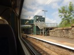
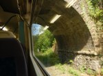
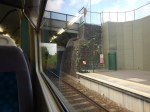
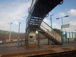
Bi-Mode Good, Tri-Mode Better
The title of this post, is the same as that of this article on Rail Engineer.
It is an informative article about the creation of the Class 769 trains.
These are some points.
Class 150 Performance
Class 769 performance on diesel is likely to be as good as that of a Class 150 train, if not better.
When running on electric power, they will still be capable of 100 mph.
Extensive Route And Performance Modelling
Extensive computer modelling has been carried out to make sure the train performs.
Access To The Original Designers
It appears that they were able to call in some of the original designers and that at least some of the iriginal drawings were available.
An Extensive Project
The article quotes these figures on the resources used to design the conversion.
- 60 engineers
- 45,000 engineering hours
- 2,500 drawings
- 3,500 detailed components
I suspect that this could account for the late running of the project.
Approvals
There is a large section on approvals, which is well worth a read. It looks to me, that they are making sure, that these trains fit all regulations and not those that apply to upgrades and improvements.
Noise
They are also going for better noise than a Class 15x train, which must be a good thing.
Raiding The Class 150 Parts Bin
They obviously needed exhausts for the two diesel engines, so in true Colin Chapman fashion, they looked round for something that was readily available and would do the job.
As Class 319 and 150 trains share a lot of components like bogies, the exhausts for the converted trains are from a Class 150 train.
Maintenance Costs
The new trains will obviously cost more to maintain than a Class 319 train, but will probably be cheaper to run than a Class 150 train.
The Ultimate Class 769 train.
The article indicates what could be possible.
- Air cooling
- CCTV – both saloon and forward facing
- At seat USB and power sockets
- Ethernet backbone to support engine control and Wi-Fi
- Interior and exterior rebranding
- Guard’s door control panels.
Not a bad specification for a thirty-year-old train.
Orders
There may be more orders in the pipeline.
Conclusion
I think that these trains will do what they are intended to do in a reliable and quality manner.
Tailpiece – Class 455 Flex
The article finishes with a disclosure about what might happen to the Class 455 trains.
These have been extensively refurbished and have been retrofitted with three-phase AC traction systems incorporating regenerative braking. There would be space on the intermediate trailer coach for batteries that could be charged by the regenerated energy and by the diesel engines. Such a feature could have several benefits such as being able to stop the diesel engines in terminal stations and to supplement diesel engine power when accelerating.
Could this be a four-car efficient runabout for branch lines, as they are only 75 mph trains?
Is This The Solution To A Charging Station For Battery Trains?
This page on the Opbrid web site has a main title of Automatic High Power Charging for Buses, Trucks, and Trains.
It also has a subtitle of Furrer+Frey Opbrid Charging Stations for Battery Trains.
Furrer + Frey are a Swiss railway engineering company, that design and build railway electrification systems.
The web page gives this introduction.
Since 2009, Furrer+Frey has developed a multi-modal ultra high power charging station for battery-powered vehicles that is already radically changing the way traction power is delivered to road and rail vehicles. In particular, the Furrer+Frey Railbaar system targets existing low traffic diesel traction routes as well as new light rail and tram projects. The technology applies to battery powered trams and trains (Railbaar), buses (Busbaar) and trucks (Trukbaar) with a design rooted in proven Swiss electric rail technology already successfully deployed by Furrer+Frey across Europe and the world.
The web page has an interesting image for a Swiss company.
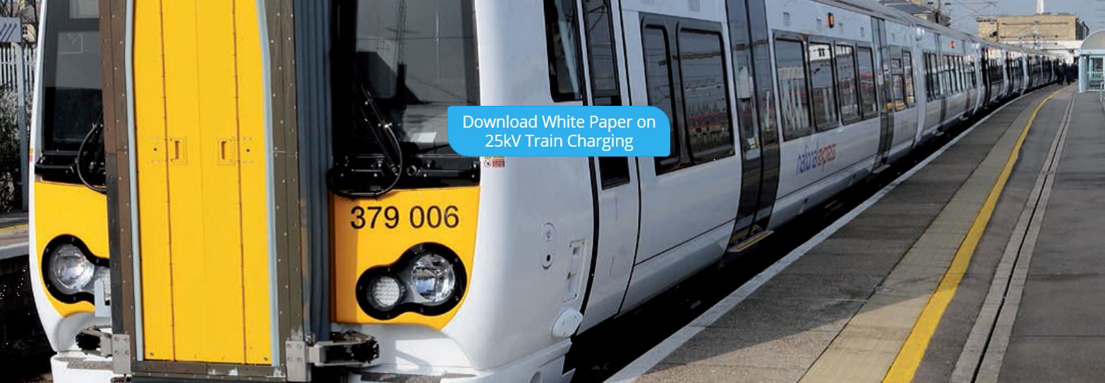
Shown is a Class 379 train, at a station, which I’m pretty sure is Cambridge.
Liverpool Street to Cambridge is a fully-electrified route, so why would a charging station be needed on this service?
I can’t think of a reason.
So I suspect, it’s just that to illustrate the web page, they needed to use a train that had the capability of running under battery power, which the Class 379 did in the BEMU trial of 2015.
It could also be that Furrer + Frey are working with Bombardier and it’s a Bombardier library picture.
But then Furrer + Frey probably work with all the major train manufacturers.
And as Bombardier have just released a new battery train, that I wrote about in Bombardier Introduces Talent 3 Battery-Operated Train, it would be logical that the two companies are working together, as battery trains will surely need charging in stations to develop longer routes.
Note the blue box in the middle of the picture. It says.
Download White Paper On 25 Kv Train Charging
If you download the white paper, you will find a very comprehensive and detailed description of how battery trains could be charged in stations. This is the introductory paragraph.
Battery-powered trains are rapidly becoming the vehicle of choice for the replacement of diesel
trains on non-electrified rail lines. Often there is not enough traffic on these lines to justify the expense of erecting overhead line equipment (OLE) along the track. In many cases, the train runs under OLE for part of its route where the battery train can charge via its pantograph. However, sometimes additional charging is required. While it is possible to erect additional kilometers of OLE for charging, it is more cost effective to charge the train via pantograph while stopped at a station using a very short length of overhead conductor rail and a 25 kV power supply.
I will now try to explain the solution.
The white paper gives this physical description of the solution.
The physical structure of the charging station is quite simple.
It consists of a short length of overhead conductor rail, approximately 20 m to 200 m in length. This length depends on the type, length, and number of battery trains that will be charging at one time. The conductor rail is supported by normal trackside posts and high voltage insulators. Insulated cables lead from the power supply to the conductor rail, with the return path from the running
rails. Furrer+Frey makes 25 kV and 15 kV overhead conductor rail systems that are ideal for this
purpose.
The design seems to use readily available components.
What Is Overhead Conductor Rail?
This picture, that I took on the Thameslink platforms at St. Pancras station, shows the overhead conductor rail, used to power the trains.
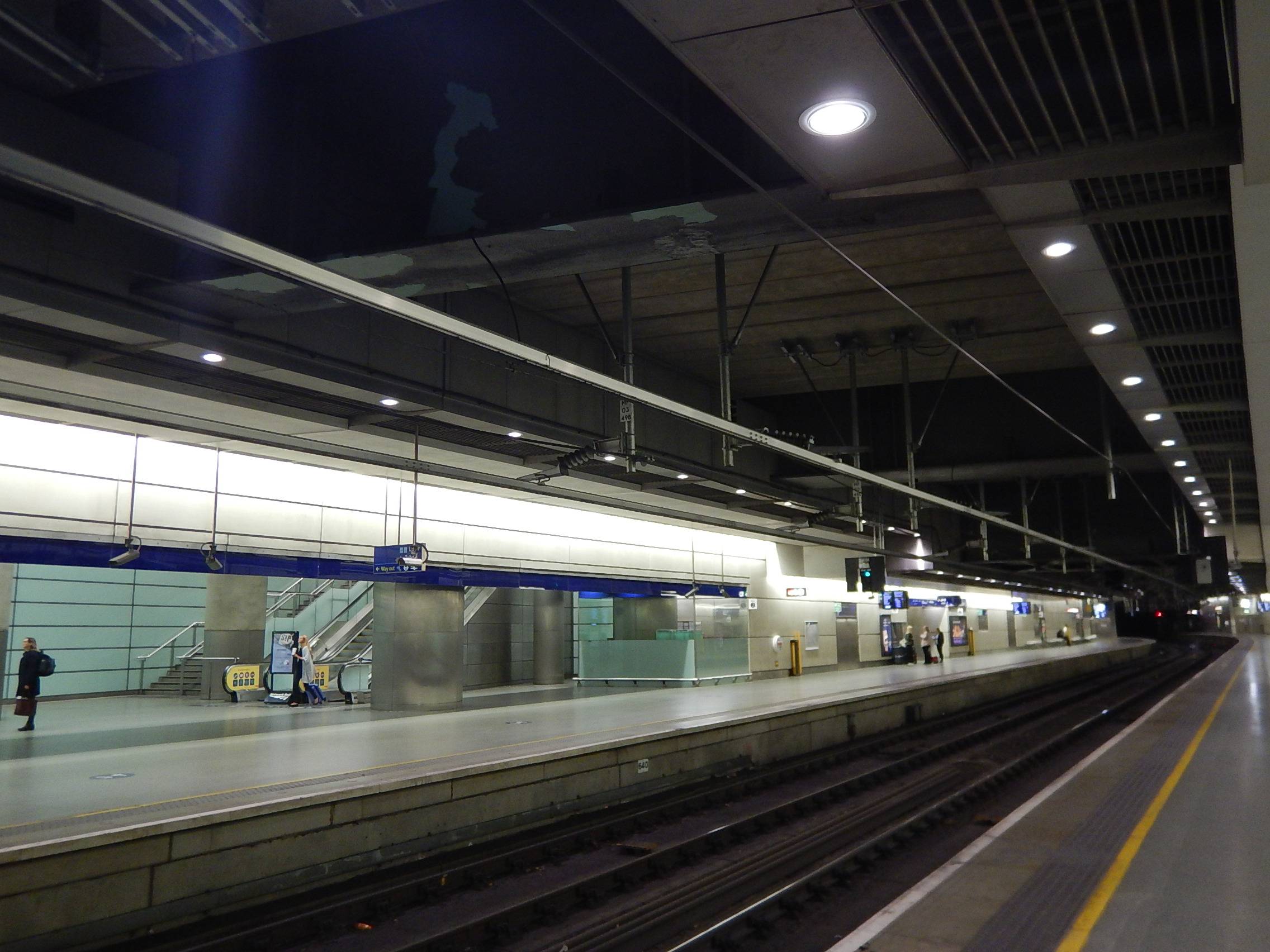
St. Pancras is one of the best places to see overhead conductor rail in London, although overhead conductor rail will be used by Crossrail in the tunnels.
How Would Overhead Conductor Rail Be Used To Charge A Train’s Batteries?
A short length of such a rail, would be mounted above the track in the station, so that it could be accessed by the train’s pantograph.
The rail would be positioned so that it was exactly over the train track, at the height required by the train.
What Voltage Would Be Used?
The normal overhead voltage in the UK, is 25 KVAC. There is no reason to believe that any other voltage would be used.
The overhead conductor rail/pantograph combination has a lot of advantages and benefits.
The Overhead Conductor Rail Is Standard
The overhead conductor rail is a standard Furrer + Frey product and it can be supported in any of the appropriate ways the company has used around the world.
This picture shows conductor rail fixed to the wall in Berlin HBf station.

Or it could be fixed to gantries like these at Gospel Oak station, which carry normal overhead wiring.
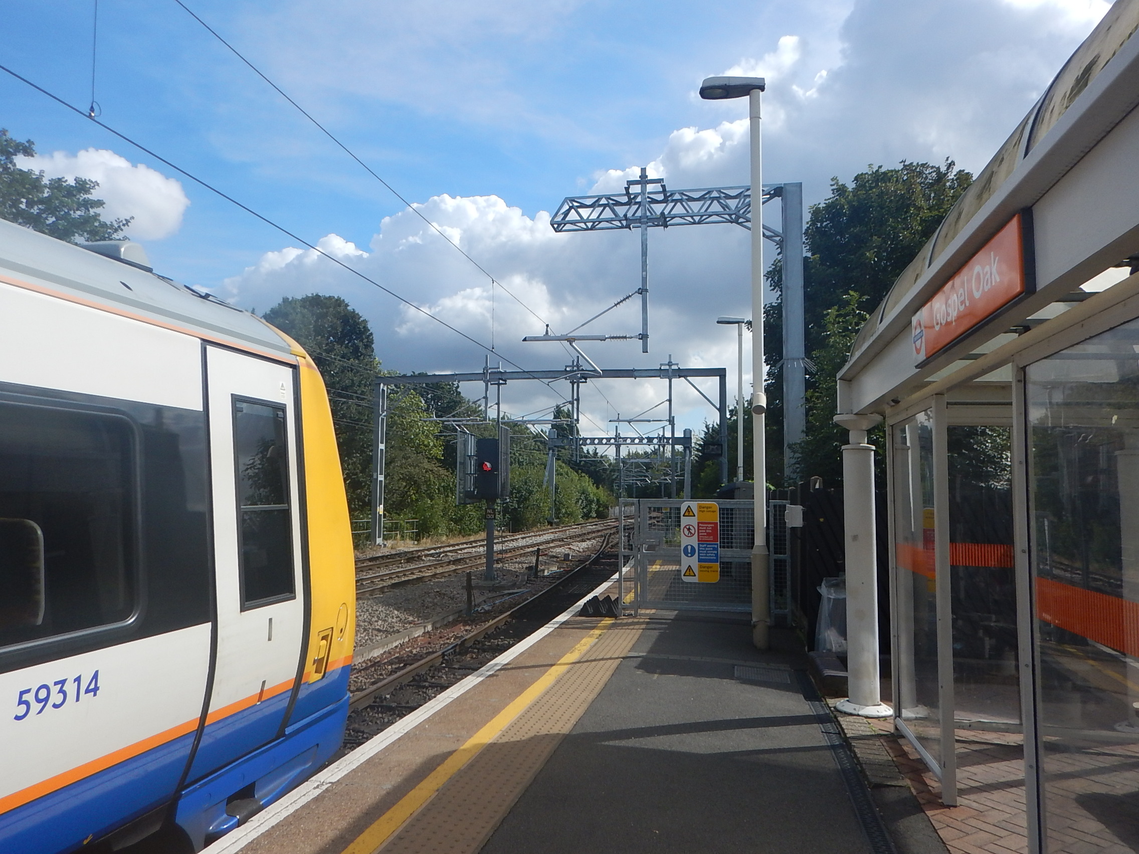
Note that gantries come in all shapes and sizes.
The Overhead Conductor Rail Can Be Any Convenient Length
There is probably a minimum length, as although drivers can stop the trains very precisely, a few extra metres will give a margin of error.
But there is no reason why at a through platform on a line served by battery trains, couldn’t have an overhead rail, that was as long as the platform.
The Train Pantograph Is Standard
The pantograph on the train, that collects the current from the overhead conductor rail can be an almost standard unit, as it will be doing the same job as it does on electrified sections of the route.
The white paper goes into this in detail.
As in the UK, our overhead line voltage is 25 Kv, the train can receive 1 MW with a current of 40 A, which is probably low enough to be below the limit of the conductor rail/pantograph combination. This would allow around 80 kWh to be transferred to the train in a five minute charge.
Could Trains Use Two Pantographs To Charge Batteries?
The white paper says that the system could handle more than one train, if the overhead conductor rail was long enough.
Bombardier’s Class 345 trains are effectively two half-trains, which each have their own pantograph.
So could a train use both pantographs to charge the batteries?
A Sophisticated Pantograph Control System Could Be Used
The train would probably have a sophisticated control system to automatically raise and lower the pantograph, so as to maximise the charge, whilst the train was in the station.
The System Should Be Safe
The overhead conductor rail would be no closer to passengers and staff, than overhead wires and conductor rail are at any other station platform in the UK.
I also suspect, that the power to the overhead conductor rail would only be switched on, if a train was being charged.
Standard Solutions Could Be Developed
One application of battery trains is to use them on a branch without electrification from an electrified line to a simple station in a town, housing or commercial development or airport..
The terminal stations would be very simple and surprisingly similar.
- One platform.
- An overhead conductor rail on gantries, a wall or some other simple support.
- A power supply for the overhead conductor rail.
A station building,, shelters and information displays could be added to the solution or designed specifically for the location.
Solutions for a wide range of countries would only differ in a few areas.
- The height of the platform.
- The gauge of the track.
- The overhead conductor rail voltage.
But I do believe that in this example of a standard system, there will be surprising commonality across the world.
As the white paper identifies, there is at least one tricky problem.
The High Voltage Power Supply
Providing high-quality, reliable high-voltage supplies may not always be that easy in some areas, so innovative electrical solutions will certainly be needed.
One solution suggested in the white paper involves using energy storage and then creating the 25 KVAC to power the overhead conductor rail.
I like this solution, as there are many applications, where these forms of independent power supplies are needed to power industrial premises, villages and equipment like flood pumps, often in remote locations. They could also incorporate a wind turbine or solar panels.
Someone will develop these systems and providing 15 or25 KVAC will be just another application.
Conclusion
I will add the conclusion from the white paper, as it says it all.
Battery trains are now available to replace diesel
trains on existing non-electrified tracks. They can
be charged using AC 25 kV 50 Hz or AC 15 kV 16,7
Hz either while running under catenary or when at
a standstill at a station using a short length of
overhead conductor rail and an appropriate power
supply. Standstill charging avoids the need to
build long stretches of catenary along a track
thereby saving money, and allowing the electrification
of track previously thought to be uneconomic
to electrify. Battery trains also enable the
use of renewable energy sources. Moving towards
green energy sources reduces harmful emissions
and noise which positively impacts climate change
and improves health
I am sure, we’ll see a lot of uses of this simple and efficient method of charging battery trains.
Bombardier Introduces Talent 3 Battery-Operated Train
The title of this post is the same as that of this article on InsideEVs.
This picture of the train is from Bombardier’s web site.
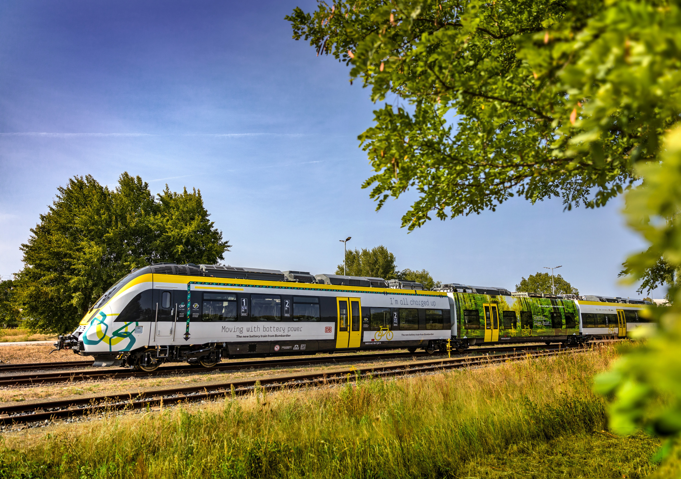
This is said.
Bombardier recently presented the Talent 3, which according to the press release, is the first of its kind to enter passenger operation in Europe in over 60 years.
The first prototype has a range of 40 km (25 miles), but the second one scheduled for 2019 will go 100 km (62 miles) on a single charge.
There’s even a nifty little video.
All the features and benefits of the train are detailed.
- Bridging gaps in electrification.
- Modular batteries, so more can be added to increase range.
- Regenerative braking to save energy.
- Lower infrastructure costs.
- Electric instead of diesel trains under city centres.
- Low noise.
- No CO2 emissions.
- Low cost of ownership.
But this is all about a Talent 3 train, that is designed to a Continental loading gauge. Wikipedia says this about the design.
The Talent 3 is based on the earlier Talent and Talent 2 designs, with a wider carbody, larger doors, and a lower floor to increase capacity and improve passenger flow at station stops. Depending on the intended service pattern, the Talent 3 can be specified with either a 160 kilometres per hour (99 mph) or 200 kilometres per hour (120 mph) top speed. Talent 3 trainsets can vary in length based on customer requirements—ÖBB ordered six-car sets with a passenger capacity of 300, while Vlexx ordered three-car sets that carry up to 160 passengers.
The picture and the video look like a three-car train.
How Large Are The Batteries On A Talent 3?
What do we know about the train?
- It appears to have three cars.
- According to this page on the Bombardier web site, the train has four batteries.
- I estimate that according to weights in Wikipedia, a three-car Talent weighs 86.5 tonnes
- A three-car Talent 3 can carry 160 passengers.
My calculation is as follows.
- 160 passengers at 90 Kg each with baggage, bikes and buggies weigh 14.4 tonnes.
- I’ll assume each battery weighs a tonne.
- This gives a total train weight of 104.9 tonnes.
At a speed of 160 kph, the Omni Kinetic Energy Calculator gives a kinetic energy of 28.8 kWh.
So four batteries of 25 kWh each would be sufficient to handle the regenerative braking energy.
What about the UK?
Bombardier’s equivalent product for the UK is the Aventra, which unlike the Talent 3 is a substantially all-new design, although it does use proven technology from previous trains.
It has also received six orders for a total of over 400 trains.
I have always thought, that after the successful BEMU trial with a Bombardier Class 379 train, that batteries will become an important part of rail technology and they will feature in the design of the Aventra.
You may think, that looking at the video, that we’ll have trouble with the UK’s small loading gauge putting the batteries on the roof of the train, but the actual size of batteries is not large and they can go underneath.
I sometimes wonder, If the reason for the delay of the Class 710 trains, is that when they are successfully running, Bombardier will finally come clean in the UK, about how batteries are used on the Aventra. You wouldn’t want the trains to be unreliable, so they are making sure that all systems, including the important batteries are 100 % reliable.
In Don’t Mention Electrification!, I state why I believe that the Barking Riverside Extension of the Gospel Oak to Barking Line could be built without electrification.
So I’m fairly certain that the Class 710 trains are designed to run this section of the route on battery power.
Did The Queen Ever Ride In This Train?
These pictures show the British Rail BEMU, which was an experimental two-car battery electric multiple unit, that ran on the Deeside Railway between Aberdeen and Ballater stations, in the late 1950s and early 1960s.
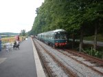
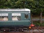
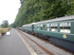
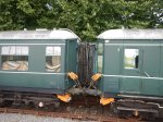
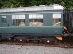
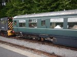


It is now parked at the Royal Deeside Railway awaiting restoration.
As the bodywork is aluminium, it struck me that it wouldn’t be an impossible restoration project.
Someone, I spoke to, said the biggest problem and probably expense were the batteries.
Perhaps, they could use some recycled batteries from electric buses or other vehicles, which some companies are going to use as house storage batteries.
A Memory From A Lady
I travelled to the Royal Deeside Railway on a bus and sat up front on the top deck. Next to me was a lady, who was perhaps in her seventies like me, who remembered using the train several times.
From what she said, it appeared to work reliably for a number of years.
Did Her Majesty Ever Use The Train?
No-one at the Royal Deeside Railway has any proof, that the Queen ever rode in the train.
But they are pretty sure, that the Queen Mother used the train. Apparently, she liked the steady speed as it proceeded through the countryside.
Conclusion
With the current developments in battery transport, I feel that this prototype might well be worth restoring to operation condition.
Hydrogen Is Really Happening
The title of this post, is the same as that of this opinion in Energy Voice.
It is a good summary of where we are with hydrogen.
One interesting point of several is that researchers in the US and Spain can extract hydrogen from plastic waste.
This article from FuelCellWorks describes the Spanish research.
That would surely be a real zero-carbon fuel!
Have Bombardier Got A Cunning Plan For Voyagers?
In the July 2018 Edition of Modern Railways, there is an article entitled Bi-Mode Aventra Details Revealed.
A lot of the article takes the form of reporting an interview with Des McKeon, who is Bombardier’s Commercial |Director and Global Head of Regional and Intercity.
This is a paragraph.
He also confirmed Bombardier is examining the option of fitting batteries to Voyager DEMUs for use in stations.
The Voyager family of trains has three members.
- Class 220 trains – Voyagers – 34 trains of four cars – operated by CrossCountry.
- Class 221 trains – Super Voyagers – 44 trains of four or five cars – operated by CrossCountry
- Class 222 trains – Meridians – 27 trains of four, five or seven cars – operated by East Midlands Trains.
The trains have the following characteristics in common.
- They are diesel electric multiple units.
- Each car is powered by an underfloor Cummins QSK19 diesel engine of 750 hp/560 kW.
- They are capable of 125 mph running.
- Some trains are fitted with tilting, which isn’t used.
- The trains have rheostatic braking.
- They meet or could easily meet the latest accessibility regulations for passengers of reduced mobility.
- Train length appears to be flexible and cars seem to be able to be swapped around in a particular class.
I think it is true to say that the operators have a few problems with these trains.
- Some passengers think the trains are rather cramped.
- There is also a noise and vibration problem when the engines are working hard.
- There have been problems with seawater getting in the resistor banks for the rheostatic braking on Class 220 trains at Dawlish.
- CrossCpuntry would welcome extra capacity.
- Both operators would probably welcome better fuel consumption on the trains.
How Would You Fit A Battery To A Voyager?
All these trains seem to be fitted with rheostatic braking.
Effectively, the traction motors generate electricity when they work in reverse to slow the train. On a modern train this electricity is either returned through the electrification to power other trains or stored in a battery.
But on these Voyagers, it is passed through resistors on the roof and used to heat the sky.
Consider these facts for a four-car Class 220 train.
- The train has an operating speed of 125 mph.
- Each car has its own diesel engine.
- The train has a weight of 185.6 tonnes.
- The train has seats for two hundred passengers.
- If we assume that each passenger weighs 90 Kg. with their baggage this gives a total train weight of 203.6 tonnes.
Calculating the kinetic energy of the train for various speeds gives
- 75 mph – 32 kWh
- 90 mph – 46 kWh
- 100 mph – 56 kWh
- 125 mph – 89 kWh.
Every time a train stops, this energy goes to waste.
The simplest thing to do, would be to divert this energy to an appropriately sized battery in each car. As there is four cars in the train, a battery of 50 kWh in each car would probably be sufficient.
If the battery was full, then the energy would still go to the resistors on the roof.
You’ve now got a full battery, but how would you use the energy in a productive manner?
The easiest and probably best thing to do with it, is to power the hotel functions of the train like air-conditioning, lights, doors and toilets. This is an approach taken by Hitachi on their Class 800 trains, as this diagram confirms.

The diagram is contained in this document on the Hitachi Rail web site, which is entitled Development of Class 800/801 High-speed Rolling Stock for UK Intercity Express Programme.
The document is a fascinating read.
Using the energy to power the traction motors and move the train might be possible, but I suspect it might be too complicated and expensive.
The simple system of the braking energy charging the battery and then using this energy for hotel power has advantages, both for Hitachi and Voyagers.
- The engines generally won’t need to run in a station to provide hotel power,as Des McKeon noted.
- The control electronics would be reasonably simple.
- Many of the existing expensive components like engines and traction motors probably wouldn’t need to be changed.
- There might be maintenance savings on the brakes.
- Less fuel will need to be expended to provide hotel power.
- If say the train has to halt perhaps because of a signalling or track fault, hotel power can be provided without running the engines.
- If batteries are supplying the hotel power, the train may have more power for traction.
I obviously don’t know how independent each car is from the next, but if each is independent, then there could be further advantages in converting, testing and maintaining the cars.
Conclusion
It looks to be a good plan.
In
How Can Discontinuous Electrification Be Handled?
On the proposed South Wales Metro, it is proposed to use discontinuous electrification to avoid rebuilding a lot of bridges and other structures.
This document on the KeolisAmey web site details their plans for the new Wales and Borders Franchise.
The document states this about the electrification.
Discontinuous overhead line electrification to 25 KVAC with permanently earthed sections around restricted structures, saving 55 interventions e.g. rebuilding bridges/no need for wire in Caerphilly tunnel.
So how are these interventions avoided?
The Karlsruhe Solution
On the Karlsruhe Stadbahn, similar Citylink vehicles to those proposed for Cardiff need to work on both the main line 15 KVAC used in Germany and the 750 VDC used by Karlsruhe trams.
To isolate the two voltages, a ceramic rod is placed in the catenary. The vehicle’s pantograph just rides across the voltage boundary and the vehicle’s electrical system uses whatever voltage is present.
Bridges On The South Wales Metro
These pictures show some of the types of bridges on the Cardiff Valleys Lines.

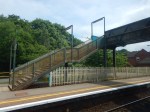


They are a real assortment.
- Some station footbridges from the Victorian era with nice castings and decoration, but no much-needed step-free access.
- Some quality brick and stone arch bridges.
- British Rail-era steel bridges, with no architectural merit
- Some modern road bridges in steel and concrete.
I also saw sizeable pipelines over the railway, which would need to be raised.
The greatest number were simple steel bridges like the one at Caerphilly station, designed to get pedestrians and cyclists, who were not using the railway, from one side of the tracks to the other.
I suspect the simplest way would be to erect two standard gantries at a safe distance of a few metres either side of the structure.
Between the two gantries would be an conductor, like this one. that I photographed in the Berlin Hauphtbahnhof.
It would be earthed, so that it offered no danger to life. There could even be extra supports under the bridge.
At each end, it would be connected to the 25 KVAC using a ceramic rod or other insulating device.
The vehicle’s pantograph would then ride from one side of the bridge to the other on its own track without being lowered.
Anything electrified at 25 KVAC would be kept at a very safe distance from the bridge.
In the earthed section, when the vehicle would be receiving no power, the vehicle would automatically switch to battery power. There would be no driver action required, except to monitor it was all working as it should.
As on the South Wales Metro, it appears that all vehicles using the lines proposed to be electrified will have their own onboard batteries, there shouldn’t be any problem.
In some ways, this discontinuous operation is a bit like using your laptop connected to the mains. When say the cleaner pulls out the plug to put in the vacuum cleaner, your laptop switches automatically to the battery.
The Caerphilly Tunnel
The Caerphilly tunnel is over a mile long. This picture shows the tunnel entrance.

It would probably be possible to electrify using a rail in the roof, but why bother if the trains running through the tunnel could go from one end to the other on their own battery power?
Trains could lower the pantograph before entry and then raise it again, when under the electrification at the other end.
This could be performed automatically using a GPS-based system.
I have also had an e-mail, which said this.
As I understand Caerphilly will have a natural bar in it but be much closer to the train roof than would be allowed with a live one.
Now there’s an idea!
A composite or earthed metal rail would be fixed to the roof of the tunnel, so that the pantograph could run smoothly from one electrified section on one side of the tunnel to the electrification on the other side, using battery power all the way.
Cost Savings
In Novel Solution Cuts Cardiff Bridge Wiring Cost, I talked about another method applied in South Wales to avoid rebuilding a bridge.
At this bridge, traditional electrification methods were used, but the need to demolish the bridge was avoided by using advanced insulation and protection measures.
This was my final statement.
Network Rail reckon that the solution will save about £10 million on this bridge alone, as it avoids the need for an expensive rebuild of the bridge.
The savings on this bridge will be higher as it is a large bridge over several tracks, but even saving a million on each bridge in the South Wales Metro is £55 million, which will probably be enough to build much of the infrastructure to extend to The Flourish, which would appear to not need expensive viaducts or electrification.
Should Downhill Tracks Be Left Without Electrification?
I think this may be possible on the South Wales Metro, as vehicles coming down the hills could use gravity and small amounts of battery power.
Regenerative braking would also be continuously charging the batteries.
It would certainly be simpler, than having to constantly swap between overhead and battery power on the descent, where the electrification was discontinuous.
As the lines are going to have a more intensive service, there will be additions of a second track in places to allow trains to pass.
Any electrification that could be removed from the project would be beneficial in terms of building and operational costs.
Other Routes
This post has used the South Wales Metro as an example, but I don’t see any reason, why the discontinous method and that used on the Cardiff Bridge can’t be applied to other bridges and structures over the lines on other routes in the country.
I suspect, that if they’d been used on the Gospel Oak to Barking Line, electric trains would have been running months ago!
Conclusion
Look what you get with thinking, when you have a Bonfire of the Boxes!
Has The Queen Ever Ridden In a Battery-Powered Train?
Countryfile this evening had a special program about the Queen’s Scottish house and estate at Balmoral.
One archive film, showed her arriving at Ballater station in a train hauled by a locomotive with a number that looked slightly familiar. Looking it up, it was a B1 Class locomotive, which I must have seen regularly, when I went train-spotting on the West Anglia Main Line in the 1950s.
So I looked up Ballater station in Wikipedia.
The station, which was on the 43 mile long Deeside Railway from Aberdeen, is now closed but there was this paragraph on Wikipedia under Services.
When the battery multiple unit was introduced, services were doubled to six trains a day from 21 April 1958, and Sunday service reinstated. The line was chosen for testing the unit because the stations were well spaced and the 1 in 70 ruling gradients would require substantial discharge rates.
As someone very interested in railways at the time, I’d never heard of British Rail’s use of battery trains.
Remarkably, the battery electric multiple train, is still in existence and is being preserved at the Royal Deeside Railway, not far from Balmoral.
It looks to me. that a lot of engineers at Derby, made sure that this train survived.
So what was it like?
- It was based on the Derby Lightweight diesel multiple unit.
- The North of Scotland Hydro-Electric Board initiated the design and was a joint sponsor.
- The train had an operating speed of 60 mph.
- The train was powered by two 100 kW traction motors.
- Power was provided by 416 lead-acid cells, giving a total of 440 V and 1070 A hour capacity.
- The batteries weighed nine tonnes.
- There were seats for twelve First Class passengers and a hundred and five in Second Class.
It couldn’t been that bad a train, as it ran between Aberdeen and Ballater station from 1958 to 1962.
There’s more about the train here.
Conclusion
But I can’t help wondering, if the Queen ever used the train!
