A Rusting Battery In Minnesota Could Unlock The Electric Grid Of The Future
The title of this post is the same as that of this article on the West Central Tribune.
This is the first paragraph.
A pilot project between Minnesota’s second largest supplier of electricity, Great River Energy, and a Massachusetts start-up claims to have a breakthrough in battery technology that would allow for vast expansions of renewable energy on the power grid.
The article goes on to describe Form Energy’s batteries and gives a couple of pictures.
I’m not sure, but it looks like the battery can supply 1 MW for a hundred hours.
Form Energy have impressive backers and have been secretive in the past, but the concept of using iron oxide (rust) as an energy storage medium sounds to me, to be a challenging idea.
Shell Resurrects Plans For Rejected North Sea Gasfield
The title of this post, is the same as that of this article on The Times.
This is the first two paragraphs.
Shell has submitted a revised plan for a North Sea gasfield that was rejected by regulators on environmental grounds last year.
The oil and gas major is seeking to develop the Jackdaw field, about 155 miles east of Aberdeen, which it says could produce 6.5 per cent of UK domestic gas output at peak — enough to heat 1.4 million homes. It hopes to start production in 2025 at the field, which would keep producing until 2033.
Other points in the article include.
- The platform would be unmanned.
- One of the problems with the field is that the gas naturally contains a lot of carbon dioxide.
- Shell plans to capture and store this carbon dioxide.
- The gas would be brought to shore using a nineteen mile pipeline to the Shearwater platform.
Surprisingly, the Shearwater platform is connected by the 295 mile SEAL pipeline to the Bacton terminal in Norfolk. But then Bacton is connected by the BBL pipeline to the Netherlands.
- There are depleted gas fields connected to Bacton, that can be used to store the carbon dioxide from the Jackdaw gas field.
- Shell manage the BBL pipeline.
- Shell are sitting in the middle with gas, that can be sold to the highest bidder.
It could be good for Shell without a great deal of expenditure on infrastructure.
In the short term, Jackdaw could make up our gas shortage, but as we start to blend wind-produced hydrogen into the gas network, we can export the surplus gas to the Continent. Shell might have plans for other gas fields to participate in the export of British gas to Germany, that has been replaced by wind-produced hydrogen.
It would be an interesting point, as to who would be responsible for the carbon dioxide produced by Jackdaw’s gas, that is burned in Germany. I suspect it will be the Germans.
In the long-term, when Shearwater and Jackdaw have given up all their gas, I wonder if Shell’s plans could be.
- Surround the platforms serving these fields with floating wind farms.
- Put a giant electrolyser on the Shearwater platform and bring hydrogen to the shore in the SEAL pipeline.
- Distribute the hydrogen from Bacton to the UK or through the BBL pipeline to the Continent.
I feel that Shell could do very nicely thank you out of the Jackdaw gas-field.
But it is also a plan, that produces a lot of energy, without emitting vast amounts of carbon dioxide.
A Resilient Net Zero Electricity System Achievable By 2035 But Increased Investment Required, Regen Report Finds
The title of this post, is the same as that of this article on Current News.
This is the first two paragraphs.
The technical solutions needed to operate a net zero electricity system by 2035 are available or attainable, Regen has found, though a step-change in the level of investment is still needed.
The trade body has produced a new report for National Grid ESO into a ‘day in the life’ of a fully decarbonized electricity system by 2035, which the ESO is aiming for.
The article gives a lot of figures about our electricity supply in 2035.
Consumption of electricity will be between 450 and 500TWh per year, with the following sources.
- 55-65GW of offshore wind
- 25-35GW onshore wind
- 40-50GW of solar
- 6-10GW of other renewables
- 10-15GW of low carbon dispatch
- 8-10GW of nuclear
- 8-12GW of carbon capture and storage (CCS)
- 15-25GW of fossil fuel backup.
Note.
- 450-500 TWh is 51-57 GW per hour averaged out over the year.
- They emphasise the importance of energy storage.
- No mention is made of the massive Coire Glas pumped hydro storage.
- No mention is made of hydrogen.
- As is normal, with reports like this the authors don’t keep their GW and GWh separate.
- They also don’t explain the hierarchy of MW, GW and TW, which is 1000 x steps up the scale.
The full report is at this page on the Internet.
Deutsche Bahn Is Building Overhead Line ‘Islands’ For Battery Trains
The title of this post, is the same as that of this article on Railway News.
This paragraph describes the concept.
This means, instead of electrifying a line in full, as is conventional for electric trains to draw traction power, these lines will feature intermittent electrification. The first of these lines to become operational will be in Schleswig-Holstein in December 2023. Deutsche Bahn says it will only electrify short stretches (a few hundred metres up to a few kilometres) or stations – enough to allow battery-powered trains to recharge on these lines. The state rail operator estimates that this move will mean that more than ten million train kilometres can be completed using electric rather than diesel traction in Schleswig-Holstein. The diesel trains currently in use will be decommissioned. DB estimates an annual diesel fuel saving of around ten million litres.
It looks like a simple concept will save a lot of diesel fuel.
I first talked about electrification islands to charge battery-electric trains in The Concept Of Electrification Islands, which I wrote in April 2020.
The Neighbourhood Leading A Green Energy Revolution
The title of this post, is the same as that of this article on the BBC.
These are the first two paragraphs.
An ambitious target of using hydrogen to partly power homes in the UK within three years has been set by the National Grid, the BBC has learned. On the east coast of Scotland, a small neighbourhood is playing a key role in this energy revolution.
From next year, about 300 homes in Buckhaven, and Methil, in the area of Levenmouth, will be powered by green hydrogen gas in a project called H100. Customers will be offered free hydrogen-ready boilers and cookers in the scheme, which will initially last five and a half years.
I described the H100 Project in ‘World First’: SGN Launches Bid For 300 Green Hydrogen Homes Project In Fife.
This is the home page of the H100 Fife project web site.
This Google Map shows part of Buckhaven.
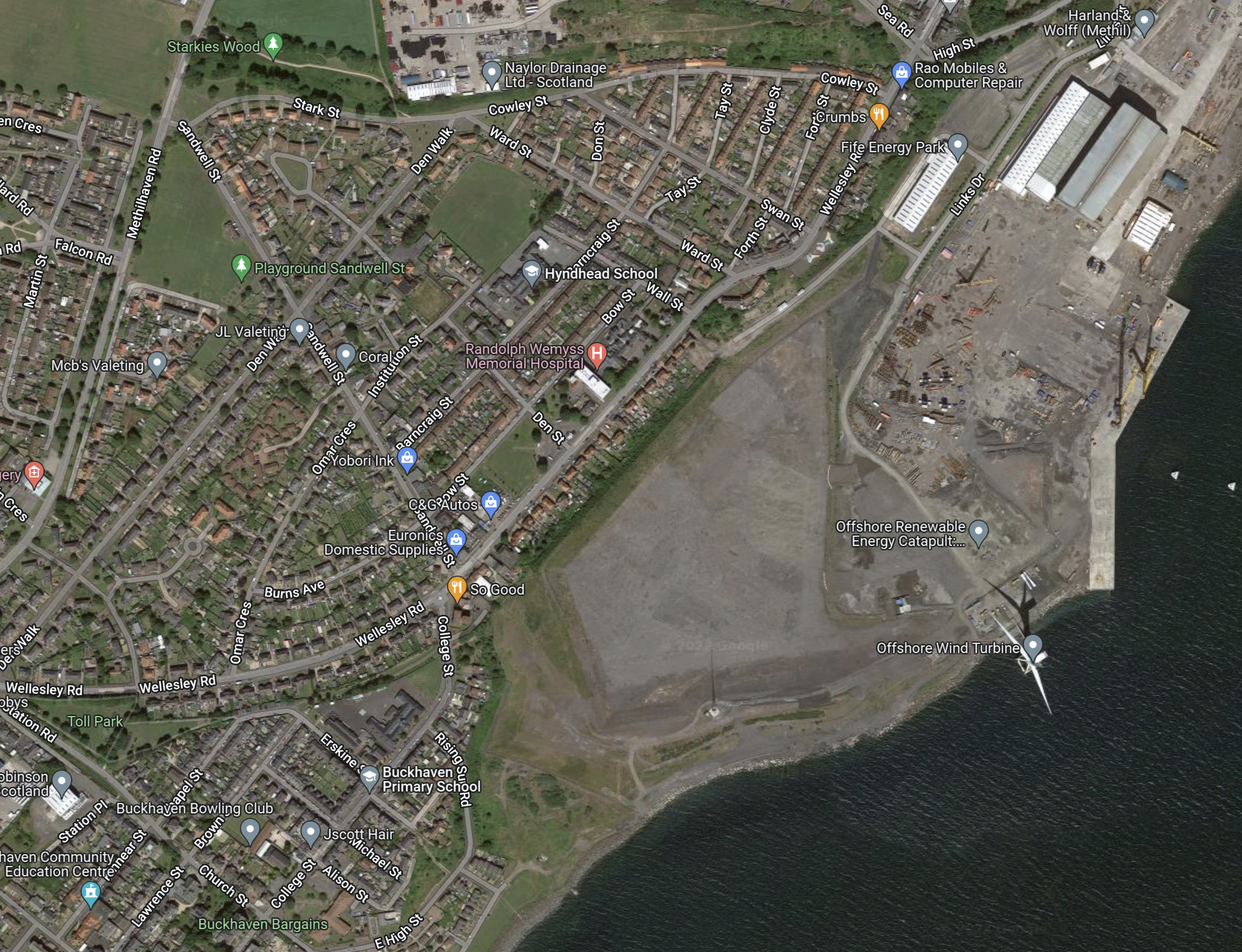
Note the wind turbine, that will produce the hydrogen is in the South-East corner of the map.
New HS2 Pilot Project Swaps Steel For Retired Wind Turbine Blades To Reinforce Concrete
The title of this post, is the same as that of this press release from High Speed Two.
These are the first three paragraphs.
Worn-out wind turbine blades destined for the incinerator will instead be used to create carbon-friendly reinforced concrete on Britain’s new high speed rail network, HS2 Ltd has said today (12.03.21).
The innovative project will swap steel rebar, traditionally used to reinforce concrete, with sections of glass fibre reinforced polymer turbine blades that have reached the end of their operational lives generating low carbon electricity.
By 2023, around 15,000 turbine blades will have been decommissioned across the UK and EU. Until now, expired blades have either been ground down to be used as building materials or sent to energy-from-waste incinerators.
Replacing reinforcing steel with sections of retired wind turbine blades is claimed to cut up to 90 % of the carbon generated by steel reinforcement.
It would appear to me, that this is a worthwhile process.
- In 2018, 295,000 metric tons of steel reinforcing bars were produced in the UK.
- Retired blades don’t end up in landfill or incinerators.
- Could we export them as eco-friendly reinforcing bars, to countries with smaller wind industries.
As we have more wind farms, than most other countries, we will probably have more blades to recycle, so perhaps we should research other secondary uses for these blades.
Highland Council Forges Green Hydrogen Pact
The title of this post, is the same as that of this article on renews.biz.
These are the first two paragraphs.
Getech subsidiary H2 Green has signed a memorandum of understanding (MoU) with the Highland Council in Scotland aimed at creating a regional network of green hydrogen hubs across the Scottish Highlands.
Under the terms of the MoU, H2 Green and the Highland Council will produce a regional plan to develop a network of green hydrogen hubs at optimal locations across the region.
The first hub appears to be in Inverness, as I wrote in Hydrogen Hub Plan Will Cut Transport Sector Emissions In The Highlands.
But that is only the start.
- Green hydrogen will be used in transport in the Highlands.
- By-products like oxygen and heat will be distributed.
- Delivery of Highland decarbonisation will be planned.
- SGN Commercial Services will service large-volume customers.
- Agreements are in place for Eversholt Rail to deploy their hydrogen-powered trains on the Far North and West Highland Lines of Scotland.
This statement from Jonathan Copus of Getech, sums up the objectives of the hydrogen project.
These activities combined with the Highland Council initiative are set to establish the Highlands as the leading UK-centre for decarbonisation and innovation; they will also support job creation, deliver energy security and provide a sustainable path for the region’s net zero transition.
I believe that a similar approach could be taken in other parts of the UK. Cornwall, East Anglia, Lincolnshire, much of Wales and the Borderlands between England and Scotland come to mind.
Each region will probably, decarbonise slightly differently and each will develop more and more innovative ways to use the hydrogen.
Conclusion
Hydrogen will play a large part in the decarbonisation of the UK.
Plan For New Nuclear Reactors At Wylfa And Trawsfynydd A Step Closer As Natural Resource Wales Looks At Designs
The title of this post, is the same as that of this article on nation.cymru.
These are the first two paragraphs.
Plans for new nuclear power stations at Trawsfynydd and Wylfa have taken a step closer after the UK Government asked government regulators to assess designs for the reactors.
Natural Resources Wales will be among those assessing the designs by Rolls-Royce, with both Wylfa and Trawsfynydd have been named as potential sites for housing them within the UK.
These are points about the reactors.
- They will cost £1.8 billion each.
- They are capable of powering a city the size of Cardiff, which has a population of about half-a-million.
- I’ve read elsewhere that the reactors are planned to have a nameplate capacity of 470 MW.
The article did mention, that the Nimbys were lining up.
The Wylfa Site
The original Wylfa power station was a Magnox nuclear station generating 980 MW, that was decommissioned in 2015.
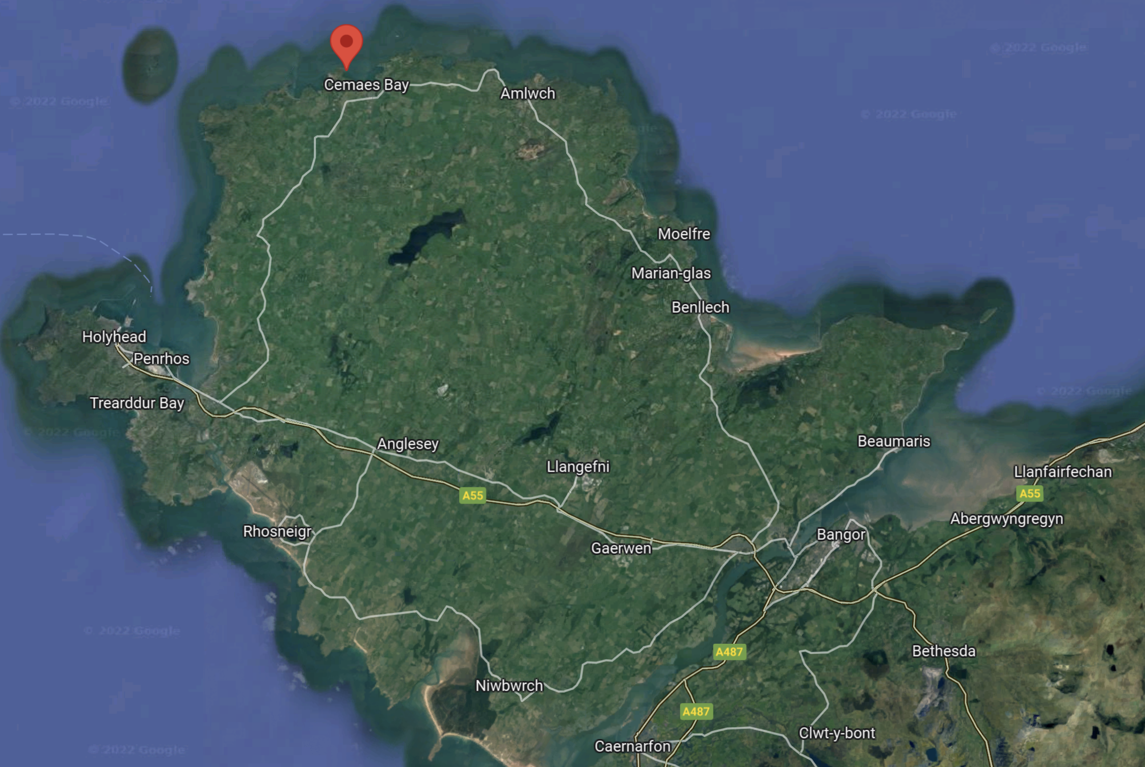
This Google Map shows the location of the site on Anglesey.
This second Google Map shows the site in more detail.
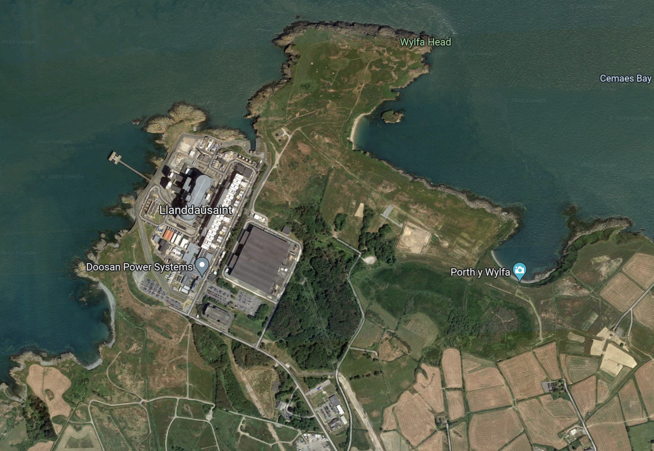
The power station doesn’t appear to have had a rail link, but there is a railway line a few miles away, with sidings that might have been used to handle fuel flasks.
There has been a proposal for a hybrid plant consisting of a wind farm and small modular nuclear reactors, which is described in this Wikipedia section, where this is said.
In January 2021, Shearwater Energy presented plans for a hybrid plant, to consist of a wind farm and small modular reactors (SMRs), to be installed adjacent to the existing Wylfa power station but separate from the proposed Wylfa Newydd site. Shearwater has signed a memorandum of understanding with NuScale Power for the SMRs. The plant could start generation as early as 2027 and would ultimately produce up to 3 GW of electricity and power a hydrogen generation unit producing up to 3 million kg of hydrogen per year.
Note.
- Wylfa Newydd was a proposal by Hitachi to build a nuclear station on the site.
- Shearwater Energy is a UK developer of energy opportunities.
- NuScale Power is an American company with its own design of small modular nuclear reactor.
In Holyhead Hydrogen Hub Planned For Wales, I talked about hydrogen and the port of Holyhead.
The Trawsfynydd Site
The original Trawsfynydd power station was a Magnox nuclear station generating 470 MW, that was decommissioned in 1991.
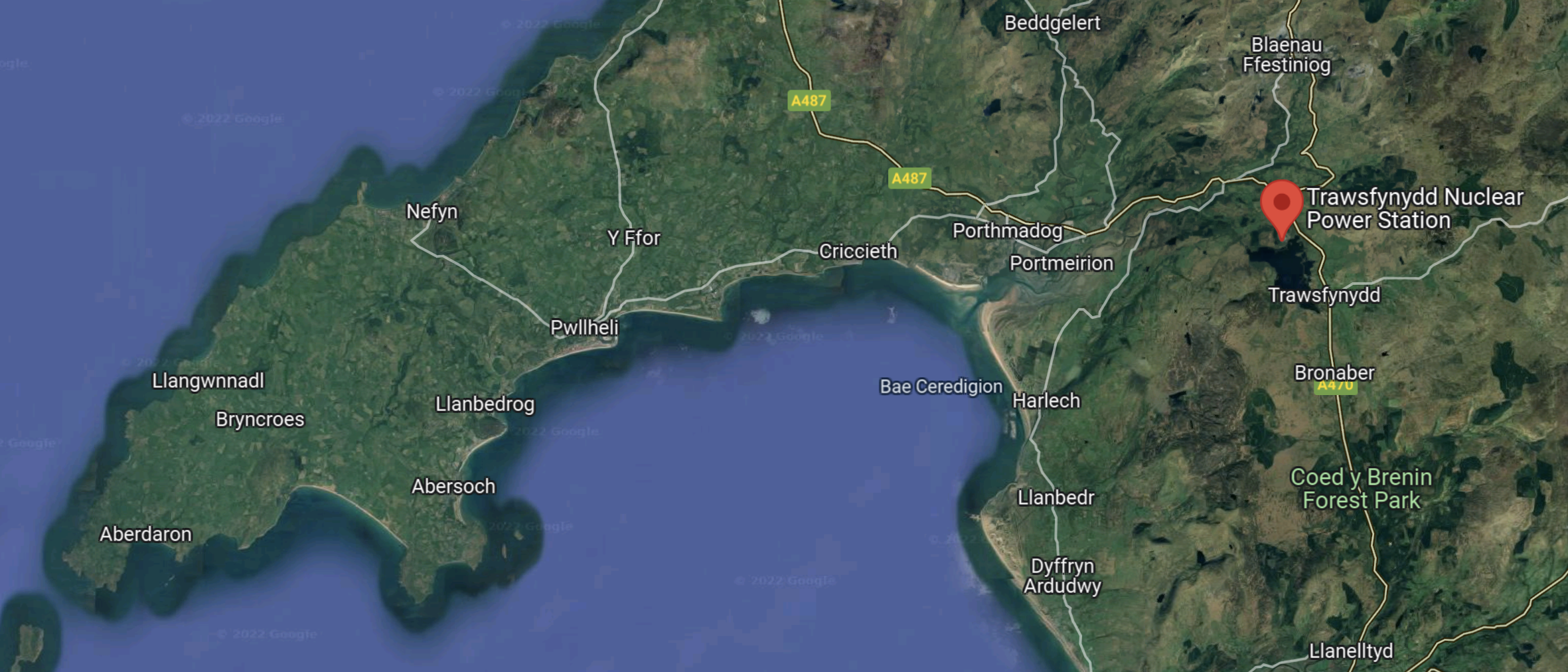
This Google Map shows the location of the site in North Wales.
This second Google Map shows the site in more detail.
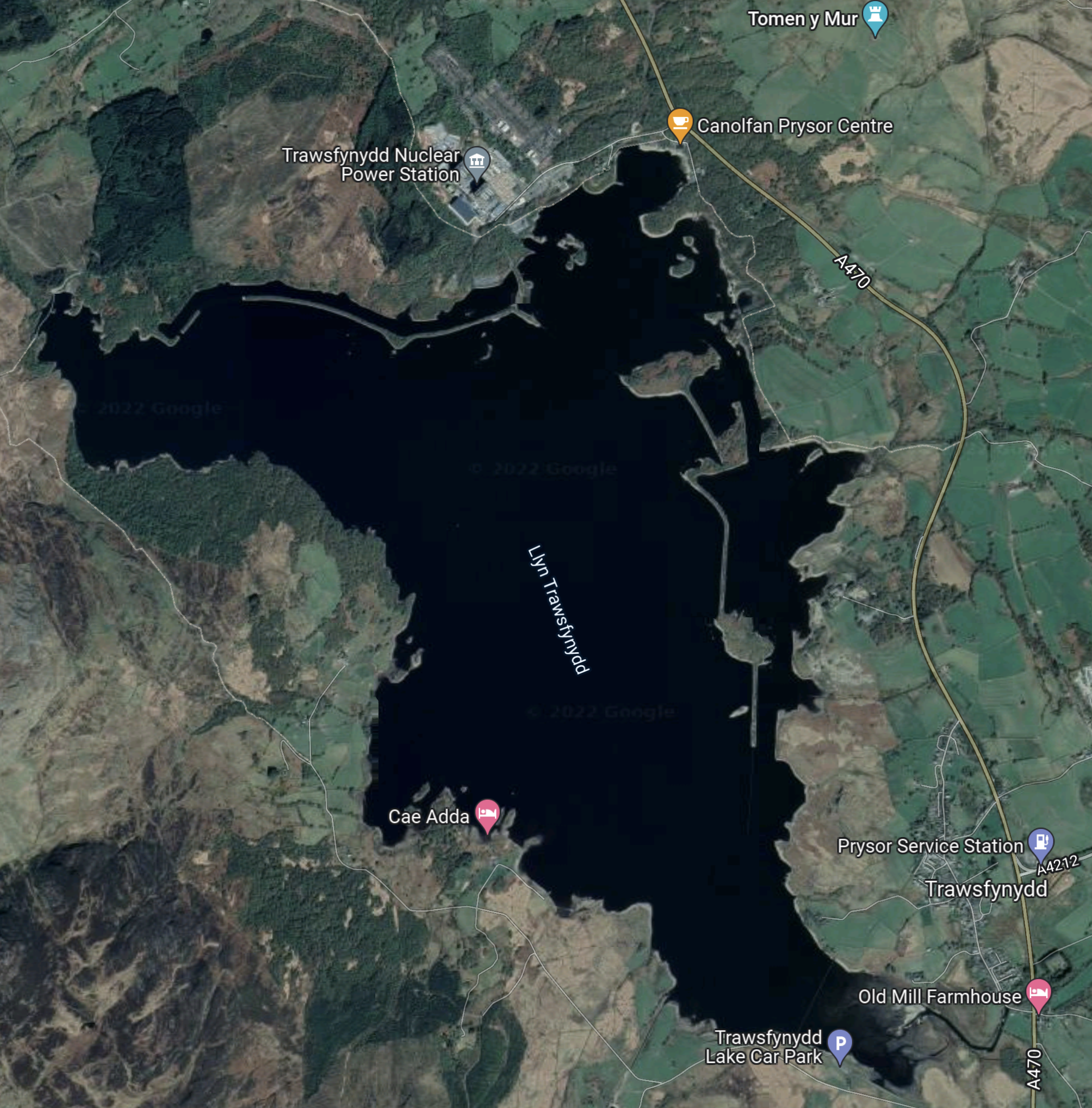
Note.
- The power station was built on the Northern shore of Llyn Trawsfynydd.
- Llyn Trawsfynydd is a man-made lake, that was built in the 1920s to supply water to the 24 MW Maentwrog hydro electric power station.
- There is a railway from near the site, that connects to the Conwy Valley Line at Blaenau Ffestiniog.
The Trawsfynydd site is a lot more than just a decommissioned Magnox power station.
Pumped Energy Storage In Snowdonia
Currently, there are two existing pumped storage in Snowdonia.
- Dinorwig power station, which is often called Electric Mountain, which has a capacity of 9.1 GWh.
- Ffestiniog power station, which has a capacity of around 1 GWh. If anybody has a better figure let me know!
A third scheme is under development at Glyn Rhonwy, which could have a capacity of 700 MWh.
Looking at the size of Llyn Trawsfynydd, I do wonder, if it could be the top lake of a future pumped storage scheme.
- Llyn Trawsfynydd, contains 40 million tonnes of water.
- There is a head of 190 metres.
That could give energy storage of 20 GWh. That sounds a lot of GWhs! But with two possible small modular nuclear reactors at possibly 500 MW each nearby and some help from windfarms, it could be filled within a day, if there is a suitable low-level reservoir.
Rolls-Royce And The Duisburg Container Terminal
In Rolls-Royce Makes Duisburg Container Terminal Climate Neutral With MTU Hydrogen Technology, I showed how Rolls-Royce and its subsidiary were providing an innovative climate neutral solution for Duisburg Container Terminal in Germany.
A North West Wales Powerhouse
Could Rolls-Royce be planning a Duisburg-style solution for North West Wales.
- Small modular nuclear reactors at Wylfa and Trawsfynydd.
- Hydrogen electrolysers to create hydrogen for the Port of Holyhead and heavy transport.
- Adequate pumped hydro storage for surplus energy.
But there could be little serious above-ground construction.
Conclusion
Something is awakening in North West Wales.
Gelion Claims Zinc-Bromine Gel Batteries Will Replace Lithium-Ion
The title of this post, is the same as that as this article on RideApart.
These are the first two paragraphs.
Battery technologies are evolving at a rapid pace—and for good reasons. With the automotive world moving toward electrification, companies need to find solutions for producing electric vehicles on a massive scale. While lithium-ion battery technology rules the roost today, that isn’t stopping firms from developing the next big leap forward.
From solid-state power units to structural batteries to sci-fi-worthy quantum batteries, there’s no shortage of ideas and concepts. However, the Australian company Gelion Technologies believes it found a more affordable and durable approach with its zinc-bromine gel battery. Unlike lithium-ion units, the material found in Gelion’s design isn’t rare, expensive, or potentially flammable.
It’s yet another development coming out of Australia.
Wind Farms On The East Coast Of Scotland
This map shows the proposed wind farms off the East coast of Scotland.
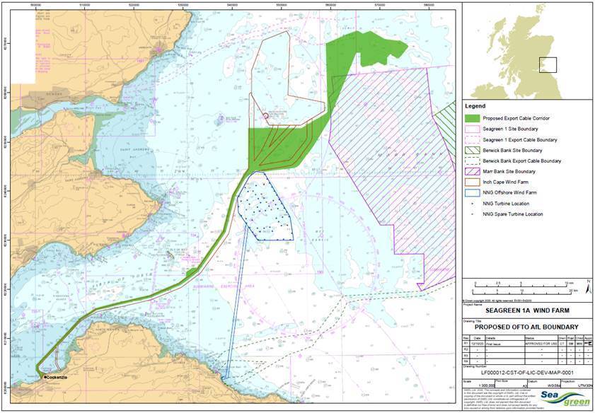
There are five wind farms in the map.
- The green area is the cable corridor for Seagreen 1a
- Inch Cape is the odd-shaped wind farm to the North and West of the green area
- Seagreen at the top of the map, to the North of Inch Cape.
- Marr Bank with the pink NE-SW hatching
- Berwick Bank with the green NW-SE hatching
- Neart Na Gaoithe is edged in blue to the South of the green area.
Berwick Bank and Marr Bank are both owned by SSE and appear to have been combined.
These are some more details on each of the now four wind farms.
Seagreen
These are details of the Seagreen wind farm.
- Seagreen will be Scotland’s largest and the world’s deepest offshore wind farm when complete.
- The first phase will have 114 turbines and a capacity of 1075 MW.
- It will connect to the grid at a new substation at Tealing near Dundee.
- The cables will run to the North of the Inch Cape wind farm.
- It will be completed in 2023.
- The second phase (1a), will have 36 turbines.
- It may have larger turbines.
- The cables will run in the green area to Cockenzie in East Lothian.
This press release from SSE is entitled Another Milestone For Scotland’s Largest Offshore Wind Farm As 4,800 Tonnes Offshore Platform Completed.
This is the first paragraph.
The topside forms the backbone of the offshore wind farm. At 40 metres long, 45 metres wide and 15 metres high, the heavyweight superstructure’s role is to collect and manage 1,075MW of power generated by the 114 Vestas wind turbines before transferring it ashore via around 60km of offshore subsea cabling.
This platform is used to connect the 114 turbines to the shore.
Inch Cape
This paragraph from the home page of the Inch Cape web site, describes the wind farm.
The Inch Cape Offshore Wind Farm, currently in late stage development, will see up to 72 turbines located 15 km off the Angus Coast and connect to the National Grid at Cockenzie, East Lothian. Once complete, it will be one of Scotland’s largest single sources of renewable energy and power up to 1 million homes with clean electricity.
The home page says it will generate up to 1 GW of electricity.
Neart Na Gaoithe
This sentence for the Wikipedia entry for the Neart Na Gaoithe web site describes the wind farm.
It is being developed by Mainstream Renewable Power at a cost of £1.4bn. Offshore work began in 2020, with completion planned for 2023.
The Wikipedia entry says it will generate up to 450 MW of electricity.
Berwick Bank
These two paragraphs from the project page of the Berwick Bank web site describes the wind farm.
Located in the North Sea, in the outer Firth of Forth, Berwick Bank Offshore Wind Farm has the potential to deliver up to 4.1 GW of installed capacity, making it one of the largest offshore opportunities in the world.
Berwick Bank Wind Farm is in the development stage and previously the project was comprised of two separate proposals, Berwick Bank Wind Farm and Marr Bank Wind Farm. Following initial rounds of consultation, it has been decided to combine our proposals into one single opportunity – Berwick Bank Wind Farm.
At 4.1 GW, Berwick Bank is a big wind farm.
The capacity of the four farms can be summarised as follows.
- Seagreen – 1075 MW
- Neart Na Gaoithe – 450 MW
- Inch Cape – 1000 MW
- Berwick Bank – 4100 MW
This gives a total of 6625 MW.
