Gore Street Energy Storage Fund Seals ‘Landmark’ Acquisition In Germany
The title of this post, is the same as that of this article on Proactive Investors.
This is the first paragraph.
“This is a landmark acquisition with compelling fundamentals which not only demonstrates our entry into new markets but also increases our operational cash generating assets, and further diversifies Gore Street’s portfolio.”
I would assume that this is a quote from someone at Gore Street.
A more engineering approach is taken in this article on Renewsables Now, which is entitled Gore Street Buys 90% Stake In 22-MW/28-MWh Battery In Germany.
Gore Street Energy Storage Fund certainly have ambition.
Where Is Zaporizhzhya Nuclear Power Plant?
I have been looking on Google Maps to find Zaporizhzhya Nuclear Power Plant in Ukraine.
This Google Map shows the power plant with respect to the Black Sea.

Note.
- Zaporizhzhya Nuclear Power Plant is marked by the red arrow above the Black Sea., at the top of the map.
- The River Dnieper runs between the Black Sea and the power plant.
- Crimea is the piece of land with Sevastopol marked on it.
This second Google Map shows the location of the power plant.

Note the wide River is the Dnieper, with what looks to be a series of breakwaters or a port enclosing a square patch of water towards the West.
This third Google Map shows the power plant in the North-East corner of the port.

Note that each of the red dots is one 3 GW nuclear reactor, which were built in the 1980s.
It appears that at this time of year, that the prevailing wind is in the East so Moldova will get any radiation.
But luckily, at the time of writing, everything seems OK.
Scotland’s Energy Storage
I have been using the web sites of Drax Group, SSE Renewables and ILI Group, and this page from Strathclyde University to look at various hydro-electric schemes to store energy using the tried-and-tested method of pumped hydro.
I have analysed these schemes.
Affric/Beauly
The scheme is now owned by SSE Renewables and has a page on their web site, which introduces the scheme like this.
Situated about 16 kilometres to the west of Inverness, Beauly is the gateway to the Affric/Beauly hydro electric scheme.
Currently, it generates a maximum power of 100.3 MW.
My analysis in Repurposing The Affric/Beauly Hydro-Electric Scheme, showed the following.
- Research from Strathclyde University, says that the Affric/Beauly scheme could support 78 GWh of pumped storage in one scheme at Fasnakyle.
- Adding pumped storage facilities to the Affric/Beauly hydro-electric scheme, with a capacity of upwards of a conservative 50 GWh, should be possible.
Generating capacity and system operation could be improved by replacing some or all of the 1950s and 1960s turbines with modern units and using modern control systems.
The Affric/Beauly hydro-electric scheme could be augmented by upwards of 50 GWh of storage.
Balliemeanoch
This new scheme is being developed by the ILI Group.
From what is published in the press. it appears to be a giant 1.5 GW/45 GWh project.
In Thoughts On The Balliemeanoch Pumped-Hydro Scheme, I analyse the plan.
The Balliemeanoch hydro-electric scheme could add 45 GWh of storage.
Balmacaan
This new scheme is being developed by SSE Renewables.
My searches in A Possible Balmacaan Pumped Storage System, showed the following.
It has a 600 MW generating capacity and I suspect would have about 15-20 GWh of storage.
The Balmacaan hydro-electric scheme could conservatively add upwards of 15 GWh of storage.
Breadalbane
The scheme is now owned by SSE Renewables and has a page on their web site, which introduces the scheme like this.
The Breadalbane scheme is set in the mountainous region around Loch Lyon, Loch Tay and Loch Earn in Perthshire.
Currently, it generates a maximum power of 168.4 MW.
My analysis in Repurposing The Breadalbane Hydro-Electric Scheme, showed the following.
- Research from Strathclyde University, says that the Breadalbane scheme could support 12 GWh of pumped storage in one scheme at Ben Lawers.
- I believe a similar scheme could be built South of Loch Tay to add a similar amount of pumped storage capacity.
As with the Beauly/Affric scheme, generating capacity and system operation could be improved by replacing some or all of the 1950s and 1960s turbines with modern units and using modern control systems.
The Breadalbane hydro-electric scheme could be augmented by upwards of 12 GWh of storage.
Coire Glass
This new scheme is being developed by SSE Renewables and the project has its own web site, which introduces the scheme like this.
Coire Glas is a hydro pumped storage scheme with a potential capacity of up to 1500MW. Coire Glas is an excellent pumped storage site with a large lower reservoir (Loch Lochy) and a significant elevation of more than 500m between the lower and the new upper reservoir site over a relatively short distance.
It is planned to generate a maximum power of up to 1.5 GW for twenty hours, which indicates an energy storage capacity of 30 GWh.
In SSE Renewables Launches 1.5GW Coire Glas Construction Tender, I talk about the current status of the project.
The Coire Glas hydro-electric scheme could add 30 GWh of storage.
Conon
The scheme is now owned by SSE Renewables and has a page on their web site, which introduces the scheme like this.
The Conon scheme lies within the northwest Highlands, broadly between Inverness and Ullapool. Electricity generation started here when the Ross-shire Electricity Supply Company built the small Falls of Conon hydro electric power station in the 1920s.
Currently, it generates a maximum power of 107.2 MW.
My analysis in Repurposing The Conon Hydro-Electric Scheme, showed the following.
- Research from Strathclyde University, says that the Conon scheme could support up to 131 GWh of pumped storage.
- Adding pumped storage facilities to the Conon hydro-electric scheme, with a capacity of upwards of a conservative 30-40 GWh, should be possible.
As with other schemes, generating capacity and system operation could be improved by replacing some or all of the 1950s turbines with modern units and using modern control systems.
The Conon hydro-electric scheme could be augmented by upwards of 30 GWh of storage.
Corrievarkie
This new scheme is being developed by the ILI Group.
From the planning application it appears to be a 600 MW/14.5 GWh project.
In Corrievarkie Pumped Storage Hydro Project, I analyse the plan.
The Corrievarkie hydro-electric scheme could add 14.5 GWh of storage.
Cruachan
Cruachan is a pumped-storage power station, that is owned by Drax, which have a comprehensive web site for the power station.
- It has an output of 440 MW.
- It has an energy storage capacity of 7.1 GWh
- It can can reach full generating capacity in less than 30 seconds.
In Drax’s Plans For Cruachan, I analyse Drax’s plans, which they call Cruachan 2.
- It will be a 600 MW power station.
- It will be to the East of the current power station.
- More than a million tonnes of rock would be excavated to build the power station.
The existing upper reservoir, which can hold 2.4 billion gallons of water, has the capacity to serve both power stations.
These was my conclusions.
It looks like very good engineering to me.
- There is a good chance, that on most nights, the reservoir will be filled using wind energy
- The maximum output of the Cruachan power station has been more than tripled from 323 to 1010 MW.
- There has been no increase in the size of the Cruachan reservoir.
Scotland will now have a GW-sized hydro-electric power station.
It will not be very much smaller than Sizewell B nuclear station.
Foyers
The scheme is now owned by SSE Renewables and has a page on their web site, which introduces the scheme like this.
The current Foyers Power Station operates quite differently to conventional hydro electric power stations. Foyers hydro scheme consists of one pumped hydro power station and one hydro power station and one major dam..
Currently, it generates a maximum power of 305 MW.
My research and analysis in The Development Of The Foyers Pumped Storage Scheme, showed the following.
- Foyers is a modern pumped-hydro scheme with a capacity of 10 GWh.
- The updating of the original 1896 hydro-power station to a modern pumped-storage system in 1974 is a superb example of hydro-power engineering.
The development of Foyers power station is an example, that shows what can be done in other hydro-electric schemes around Scotland and the rest of the world.
Galloway
Galloway is a hydroelectric scheme, that is owned by Drax, which have a comprehensive web site for their two hydroelectric schemes in Scotland; Galloway and Lanark.
- Galloway has a total output of 109 MW.
- It has six power stations at Drumjohn, Kendoon, Carsfad, Earlstoun, Glenlee and Tongland.
- There is no energy storage
- It is what is known as a run-of-the-river scheme.
The scheme opened in the 1930s.
Glendoe
The scheme is now owned by SSE Renewables and has a page on their web site, which introduces the scheme like this.
In 2009, the first major hydro electric power station to be built in Scotland for almost 30 years, Glendoe on the eastern shore of Loch Ness, began generating electricity.
Currently, it generates a maximum power of 106.5 MW.
My analysis in Glendoe Hydro Power Station, led me to conclude, that engineers will look at this scheme built in the early years of this century to convert it to a pumped storage facility. It might even have been designed for conversion to a pumped storage station, as it was built after the successful conversion of Foyers power station. Comparing the size of the upper lake to Foyers and other schemes, I would estimate it could easily provide in excess of 15 GWh of storage.
The Glendoe hydro-electric scheme could be augmented by upwards of 15 GWh of storage.
Glenmuckloch
This is a small scheme promoted by Buccleuch, that generates 4 MW and stores 1.6 GWh in a disused opencast coal mine.
My analysis in The Glenmuckloch Pumped Storage Scheme, led me to this conclusion.
This project appears to have stalled, but I do like the idea of using a disused mine to store energy and the engineering behind the project.
I will ignore it in my conclusions of this post.
Great Glen
The scheme is now owned by SSE Renewables and has a page on their web site, which introduces the scheme like this.
The Great Glen runs for more than 100 kilometres from Inverness in the northeast, to Fort William in the southwest, following a geological fault line that divides north and south Scotland.
Currently, it generates a maximum power of 112.7 MW.
My analysis in Repurposing The Great Glen Hydro-Electric Scheme, showed the following.
- Research from Strathclyde University, says that the Great Glen scheme could support up to 90 GWh of pumped storage.
- Adding pumped storage facilities to the Great Glen hydro-electric scheme, with a capacity of upwards of a conservative 30 GWh, should be possible.
As with other schemes, generating capacity and system operation could be improved by replacing some or all of the 1950s and 1960s turbines with modern units and using modern control systems.
The Great Glen hydro-electric scheme could be augmented by upwards of 30 GWh of storage.
Lanark
Lanark is a hydroelectric scheme, that is owned by Drax, which have a comprehensive web site for their two hydroelectric schemes in Scotland; Galloway and Lanark.
- Lanark has a total output of 17 MW.
- It has two power stations at Bonnington and Stonebyres.
- There is no energy storage
- It is what is known as a run-of-the-river scheme.
The scheme opened in the 1920s.
Red John
This new scheme is being developed by ILI Group and the project has its own web site, which introduces the scheme like this.
Between 2007 and 2015, the total installed capacity of renewables electricity in Scotland has more than doubled. Due to its intermittent nature, the rise in renewable generation has resulted in increased demand for flexible capacity to help meet energy balancing requirements for the national grid system.
Pumped storage hydro is considered by the Directors to be the most developed and largest capacity form of grid energy storage that currently exists. This can help reduce renewable energy curtailment and therefore promote grid stability.
The web site says this about the project.
- The scheme has an output of 450 MW.
- The storage capacity is 2.8 GWh.
- The scheme has planning consent.
- The project is budgeted to cost £550 million.
- The construction program indicates that the scheme will be completed by the end of 2025.
It also has very detailed maps.
I wrote about the project in Red John Pumped Storage Hydro Project, where I came to these conclusions.
- This scheme has the output of a large gas-fired power station for just over six hours.
- The finances must add up, as no-one would back a scheme like this if they didn’t get an adequate return on their money.
It may only be a small scheme, that is a quarter of the size of the existing nearby Foyers pumped-storage scheme, but as it is shovel-ready, we should start digging.
The Red John hydro-electric scheme would add 2.8 GWh of storage.
Shin
The scheme is now owned by SSE Renewables and has a page on their web site, which introduces the scheme like this.
Shin is Scotland’s most northerly hydro electric scheme. It utilises water from a 650 square kilometre catchment area in Sutherland, including Loch Shin, and water from the River Cassley and River Brora.
Currently, it generates a maximum power of 32.1 MW.
My analysis in Shin Hydro Power Scheme, showed the following.
- I would be very surprised if any pumped storage were to be added to this scheme.
- This 1950s scheme has been partially updated.
Perhaps some more updating would be worthwhile.
Sloy/Awe
The scheme is now owned by SSE Renewables and has a page on their web site, which introduces the scheme like this.
With the exception of Cruachan Power Station which was commissioned in 1965, major work on the Sloy/Awe scheme was completed by 1963, the year the Beatles had their first No 1 hit with From Me To You – and a world away from the immediate post-war austerity being experienced when Sloy Power Station was commissioned just 14 years earlier.
Currently, it generates a maximum power of 261.9 MW.
My analysis in Repurposing The Sloy/Awe Hydro-Electric Scheme, showed the following.
- Research from Strathclyde University, says that the Sloy/Awe scheme could support up to 68 GWh of pumped storage.
- Adding pumped storage facilities to the Sloy/Awe hydro-electric scheme, with a capacity of upwards of a conservative 40 GWh, should be possible.
As with other schemes, generating capacity and system operation could be improved by replacing some or all of the 1930s and 1950s turbines with modern units and using modern control systems.
The Sloy/Awe hydro-electric scheme could be augmented by upwards of 40 GWh of storage.
Tummel Valley
The scheme is now owned by SSE Renewables and has a page on their web site, which introduces the scheme like this.
The Tummel scheme stretches from Dalwhinnie, famous for its whisky distillery, in the north, to the remote Rannoch Station in the west, and the highly-popular tourist town of Pitlochry in the east.
Currently, it generates a maximum power of 309.2 MW.
My analysis in Repurposing The Tummel Hydro-Electric Scheme, showed the following.
- Research from Strathclyde University, says that the Tummel Valley scheme could support up to 135 GWh of pumped storage.
- Adding pumped storage facilities to the Tummel Valley hydro-electric scheme, with a capacity of upwards of a conservative 40-60 GWh, should be possible.
As with other schemes, generating capacity and system operation could be improved by replacing some or all of the 1930s and 1950s turbines with modern units and using modern control systems.
The Tummel Valley hydro-electric scheme could be augmented by upwards of 40 GWh of storage.
A Simple Summary
These are deliberately conservative figures from my analysis.
- Affric/Beauly – 50 GWh
- Balliemeanoch – 45 GWh
- Balmacaan – 15 GWh
- Breadalbane – 12 GWh
- Coire Glas – 30 GWh
- Conon – 30 GWh
- Corrievarkie – 14.5 GWh
- Glendoe – 15 GWh
- Great Glen – 30 GWh
- Red John – 2.8 GWh
- Sloy/Awe – 40 GWh
- Tummel Valley – 40 GWh
Note.
- With new storage like Balliemeanoch, Balmacaan, Coire Glas, Corrievarkie and Red John, I am using published figures where they are available.
- With figures from existing schemes,I am being deliberately very conservative.
That is a total of 324.3 GWh with 107.3 GWh down to new storage
Strathclyde University’s Prediction
This page on the Strathclyde University web site, gives these figures for the possible amounts of pumped-storage that can be added to existing schemes.
- Errochty – 16
- Glasgarnock – 23
- Luichart – 38
- Clunie – 40
- Fannich – 70
- Rannoch – 41
- Fasnakyle – 78
- Tummel – 38
- Ben Lawers – 12
- Nant – 48
- Invermoriston – 22
- Invergarry – 41
- Quoich – 27
- Sloy – 20
That is a total of 514 GWh or 621.3 GWh if you include new storage.
Conclusion
Scotland and the UK, has been left a superb legacy for the future by the pioneering work of Scottish engineers and the North of Scotland Hydroelectric Board.
Most of these assets are now in the hands of two groups; Scottish and Southern Energy (SSE) and Drax Group.
Having seen several of the schemes detailed in this post, in the last few weeks, on Michael Portillo’s; Great Coastal Railway Journeys, it does seem that both groups are looking after their assets.
SSE and Drax also seem to be doing their best to publicise the success of one of the UK’s high-value, but low-profile engineering assets.
I believe that we should do a survey that would identify the following.
- What needs to be done to allow each aqueduct, dam, power station and tunnel to continue to function until a given date in the future.
- Which of the individual schemes can be updated to larger schemes or pumped storage systems.
We would then be able to device a long term plan to create a world-class hydro-electric power scheme for Scotland.
Scotland should be able to provide upwards of 400 GWh of pumped-storage.
This article on Current News is entitled Up To 24GW Of Long Duration Storage Needed For 2035 Net Zero Electricity System – Aurora.
These are the first three paragraphs.
Deploying large quantities of long duration electricity storage (LDES) could reduce system costs and reliance on gas, but greater policy support is needed to enable this, Aurora Energy Research has found.
In a new report, Aurora detailed how up to 24GW of LDES – defined as that with a duration of four hours or above – could be needed to effectively manage the intermittency of renewable generation in line with goals of operating a net zero electricity system by 2035. This is equivalent to eight times the current installed capacity.
Additionally, introducing large quantities of LDES in the UK could reduce system costs by £1.13 billion a year in 2035, cutting household bills by £26 – a hot topic with energy bills on the rise as a result of high wholesale power prices.
The report also says that long duration storage could cut carbon emissions by ten million tonnes of carbon dioxide per year.
It appears to me, Scotland can provide more than enough energy storage for the UK and the Island of Ireland, even if the seas around the British Isles were almost completed covered by wind turbines.
In addition, to the works in Scotland to update the various hydroelectric schemes, there would need to be more interconnectors around the UK and probably to close countries like Belgium, Denmark, France, Germany, the Netherlands and Norway.
There could even be an interconnector between Iceland and Scotland, so Iceland’s abundance of zero-carbon electricity could be exported to Europe.
The Glenmuckloch Pumped Storage Scheme
This article on the BBC is entitled Glenmuckloch Opencast Mine Hydro Energy Scheme Approved.
- It appears to be capable of generating 400 MW.
- Energy storage capability appears to be 1.6 GWh.
- It is to be built in a disused opencast coal mine.
It is only a small scheme, but it does seem to have planning approval.
The Scheme has a web page, which is entitled Glenmuckloch Pumped Storage Hydro
- It is being promoted by Buccleuch and 2020 Renewables and respected consultants; Arup has produced this Non-Technical Summary.
- The Non-Technical Summary is a very professional document and an interesting read.
- 2020 Renewables are now part of Forsa Energy.
- It is certainly an interesting way of removing the remains of an opencast coal mine.
According to this article on the BBC, which is entitled Buyer Sought For £250m Hydro Scheme At Glenmuckloch, the project now appears to be for sale.
Whether it will sell will depend on the cost of realising the scheme, the finance and how much the scheme will earn.
Conclusion
This project appears to have stalled, but I do like the idea of using a disused mine to store energy and the engineering behind the project.
Repurposing The Sloy/Awe Hydro Scheme
The Sloy/Awe hydro-electric scheme was built in the 1930s and 1950s, by the North of Scotland Hydroelectric Board.
- The scheme is now owned by SSE Renewables and has a page on their web site.
- There are ten individual power stations; Sloy, Sron Mor, Clachan, Allt-na-Lairige, Nant, Inverawe, Inverawe, Loch Gair, Striven and Lussa.
- There are four dams; Sloy, Allt-na-Lairige and two dams at Shira.
- Cruachan used to be part of this scheme, but is now owned by Drax.
This map from the SSE Renewables web site shows the layout of the dams and power stations.
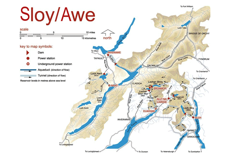
The sizes of the power stations in the scheme are as follows.
- Sloy – 152.5 MW
- Sron Mor – 5 MW
- Clachan – 40 MW
- Allt-na-Lairige – 6 MW
- Nant – 15 MW
- Inverawe – 25 MW
- Kilmelford – 2 MW
- Loch Gair – 6 MW
- Striven – 8 MW
- Lussa – 2.4 MW
This gives a total power of 261.9 MW.
It should be noted that Cruachan power station is also in this area and in Drax’s Plans For Cruachan, I talked about expanding the station from a 440 MW/7.1 GWh pumped-storage station to one of 1040 MW/7.1 GWh.
Scotland would appear to have 1.3 GW of hydro-electric power between Loch Awe and Loch Lomond.
This Google Map shows the same area as the SSE Renewables Map.
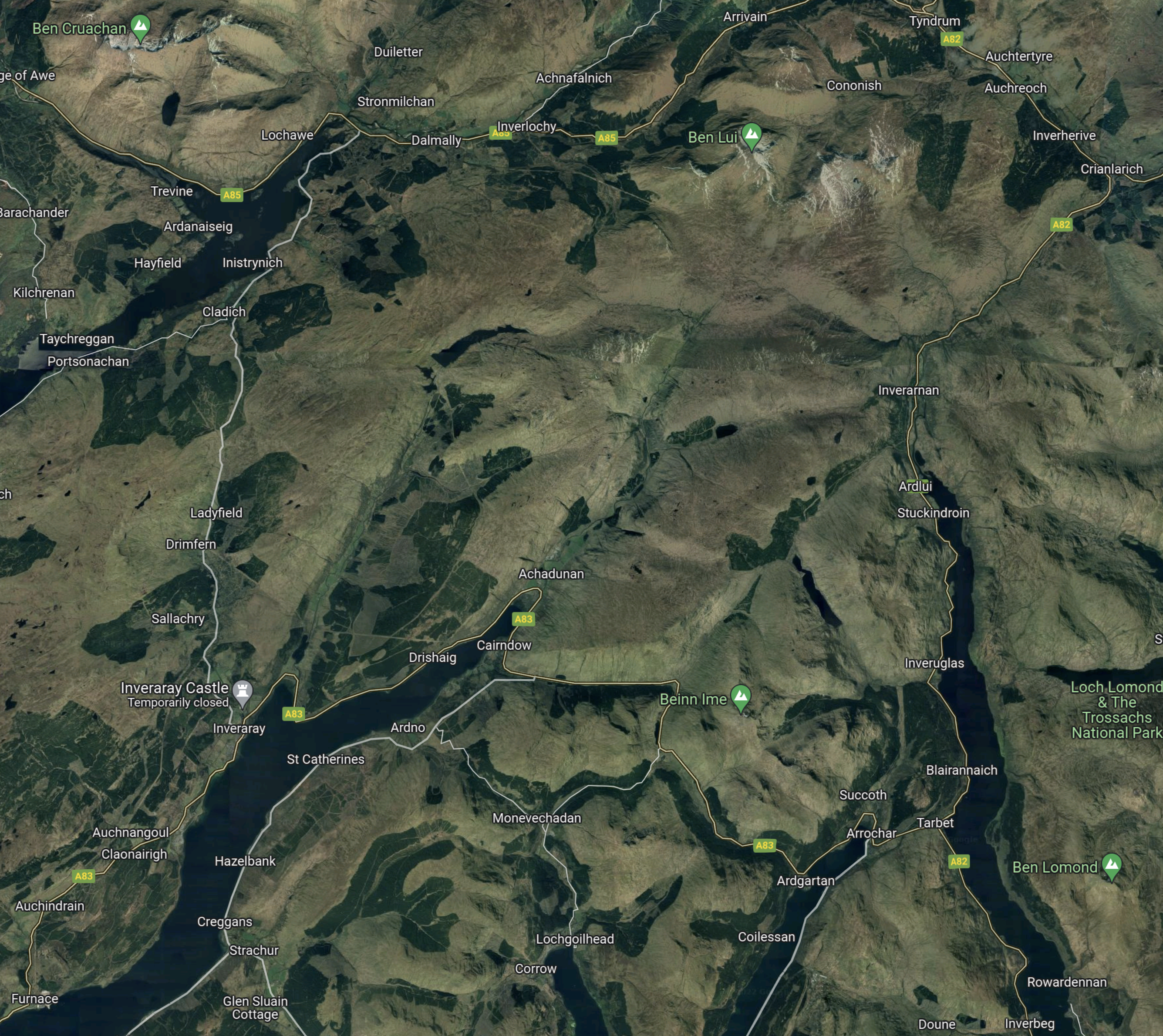
Note.
- Loch Awe, which is the sixth biggest freshwater loch in Scotland, is in the North-East corner.
- Loch Fyne, which is the longest sea loch in Scotland, is in the South-West corner.
- Loch Lomond, which is the second biggest freshwater loch in Scotland, is in the South-East corner.
- Loch Long reaches up from the South to the West of Loch Lomond.
These are four big lochs.
Strathclyde University And Pumped Storage Power For Scotland
This page on the Strathclyde University gives a list of the pumped storage potential for Scottish hydrogen-electric dams and power stations.
These figures are given for the dams and lochs in the Sloy/Awe scheme.
- Sloy – 20 GWh
- Nant – 48 GWh
It would appear that based on research from Strathclyde University, that the Sloy/Awe scheme could support over 60 GWh of pumped storage.
Water Flows In The Sloy/Awe Scheme
Looking at the SSE Renewables map of the Sloy/Awe scheme, water flows appear to be as follows.
- Loch Awe to Loch Etive via Inverawe power station.
- Cruachan reservoir to Loch Awe via Cruachan power station.
- Loch Nant to Loch Awe via Nant power station.
- Loch Nant to Loch Etive via Inverawe power station.
- Lochan Shira to Lochan Sron Mor via Sron Mor power station.
- Lochan Sron Mor to Loch Fyne via Clachan power station.
- Allt-na-Lairige reservoir to Loch Fyne via Allt-na-Lairige power station.
- Loch Sloy to Loch Lomond via Sloy power station.
All the water eventually flows into the sea to the West from Loch Etive and Loch Fyne.
Refurbishing And Repurposing The Sloy/Awe Scheme
Perhaps as the power stations are now over fifty years old, one simple way to increase the generating capacity of the Sloy/Awe scheme, might be to selectively replace the turbines, with modern turbines, that can generate electricity more efficiently.
I suspect that SSE Renewables have an ongoing program of improvements and replacements for all of their hydro-electric stations in Scotland. Some turbines at Sloy power station have already been replaced with larger ones.
Adding Pumped Storage To The Sloy/Awe Scheme
Strathclyde University picked out two places where pumped storage could be added; Sloy and Nant.
I discussed Sloy power station in A Lower-Cost Pumped Hydro Storage System and came to these conclusions.
- For £40 million, 14 GWh of pumped storage can be created at Sloy.
- But it could be bigger than 14 GWh, as this page on the Strathclyde University web site, says 20.4 GWh is possible.
- This would surely, be a project that could be first in the queue, once the environmental problems are solved.
20 GWh or even 14 GWh of pumped storage would be nice to have reasonably quickly.
As I said, this must be a high priority project.
The other project is at Loch Nant.
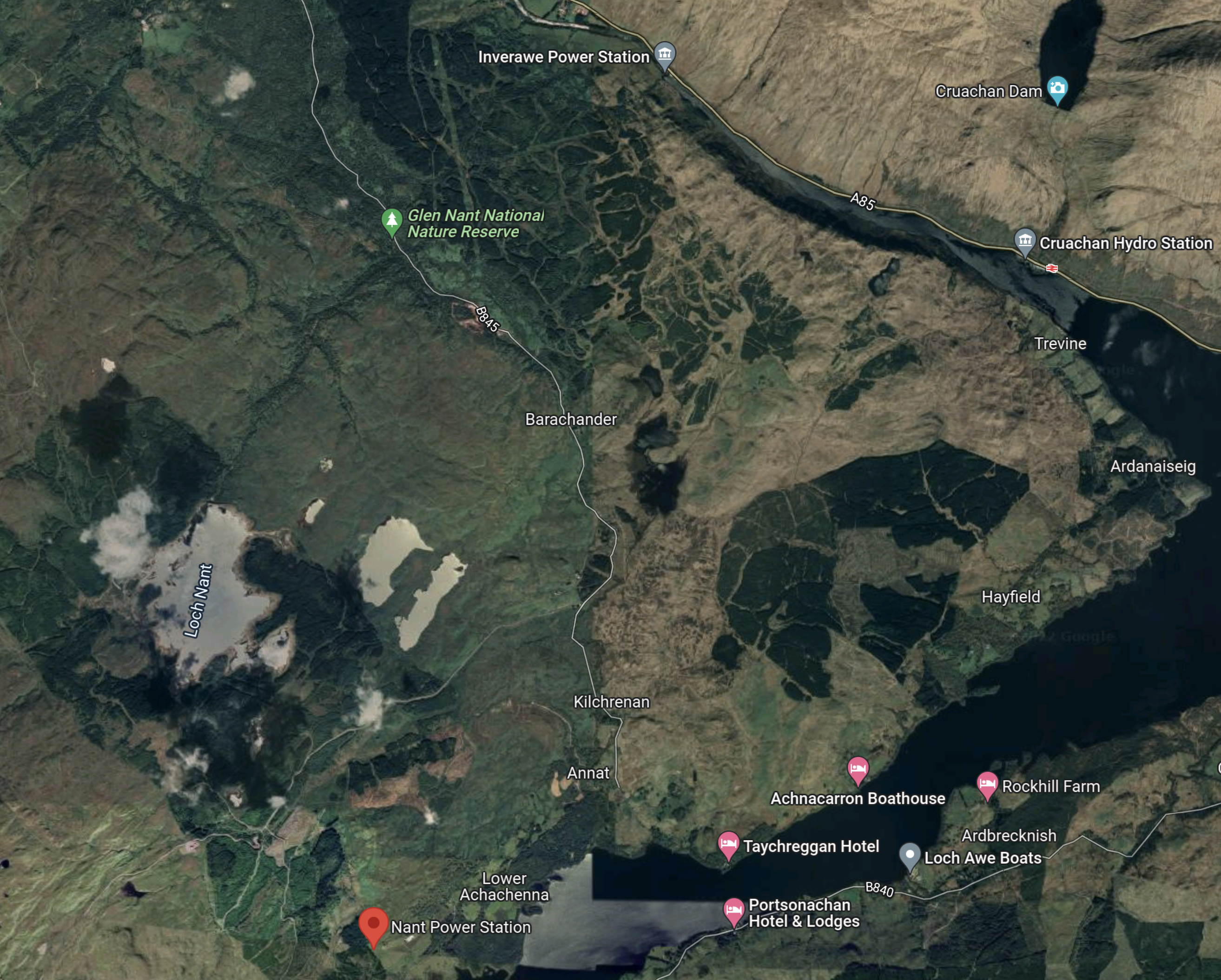
Note.
- Loch Nant is in the Western side of the map.
- Nant power station is marked by the red arrow.
- The loch to the South of the power station is Loch Awe.
- It appears that water can also go from Loch Nant to Inverawe power station to the North-East of the loch.
- Inverawe power station is on Loch Awe, which curves round Loch Nant.
- The 440MW/7.1 GWh Cruachan pumped-storage power station is on the other side of Loch Awe in the North East corner of the map, with the Cruachan dam and reservoir above.
Strathclyde University says that 48 MWh of pumped-storage could be possible at Loch Nant.
- Comparing the size of Cruchan reservoir at 7.1 GWh and the larger Loch Nant, gives me hope that Loch Nant could hold upwards of 20-30 GWh.
- From pictures on this page at Subterranea Britannica, it appears Nant power station has only a single 15 MW turbo-generator.
- Inverawe power station is a 25 MW power station with a single turbo-generator.
I suspect that pump-turbines could be installed to fill Loch Nant from Loch Awe, just as was done at Foyers, where a 300 MW pumped storage power station was created.
Conclusion
There would appear to be up to two schemes, that could each add around 20 GWh of pumped storage.
One advantage is that the waters of Loch Awe and Loch Lomond can be used for the lower reservoir.
Thoughts On The Balliemeanoch Pumped-Hydro Scheme
I first talked about the Balliemeanoch Pumped-Hydro Scheme in ILI Group To Develop 1.5GW Pumped Storage Hydro Project, which I wrote earlier this month.
I was a bit unsure as to where the high-level reservoir would be sited, although, the original report said the low-level reservoir was Loch Awe.
I then found this in an article on The Scotsman.
Project Balliemeanoch will see Lochan Airigh turned into a headpond containing 58 million cubic metres of water.
This Google Map shows Lochan Airigh.
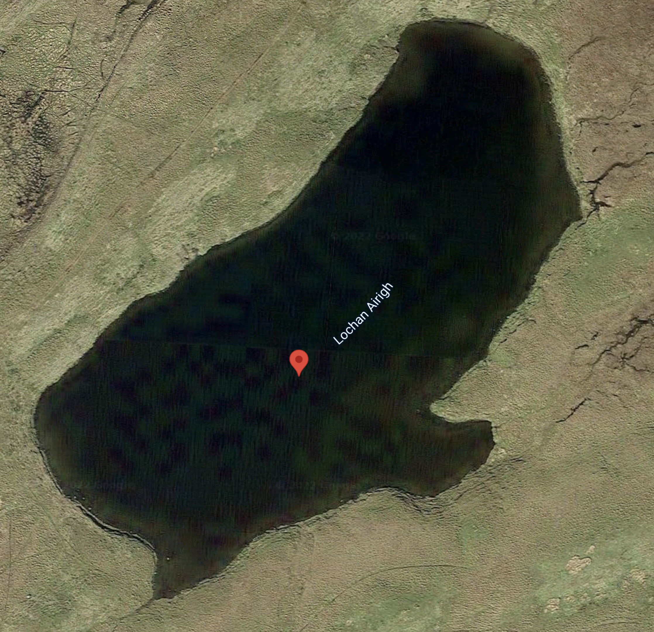
At not much more than a hundred metres across, you wouldn’t call Lochan Airigh a large loch.
But look at its position compared to the village of Ballimeanoch on the shore of Loch Awe in this Google Map.
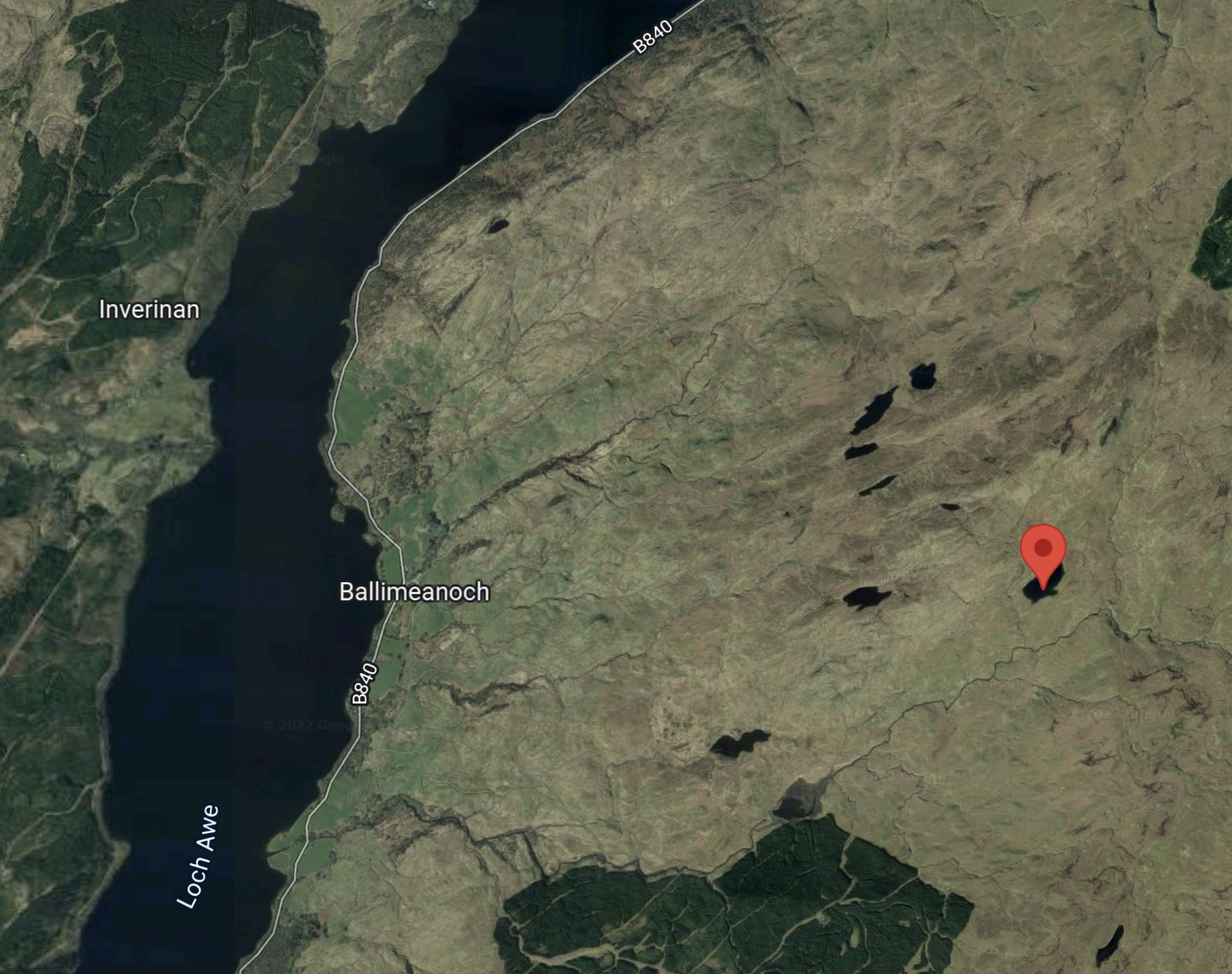
The North of Scotland Hydroelectric Board built Cruachan pumped-storage power station round the corner in Loch Awe in the early 1960s, so I would believe construction is possible.
But Cruachan is only a 7.1 GWh scheme, whereas Balliemeanoch is planned as a 45 GWh giant.
Repurposing The Breadalbane Hydro-Electric Scheme
The Breadalbane hydro-electric scheme was built in the 1950s and early 1960s, by the North of Scotland Hydroelectric Board.
- The scheme is now owned by SSE Renewables and has a page on their web site.
- There are seven individual power stations; Lubreoch, Cashlie, Lochay, Finlarig, Lednock, St Fillans and Dalchonzie.
- There are five dams; Lawers, Breaclaich, Lednock, Lubreoch and Giorra.
This map from the SSE Renewables web site shows the layout of the dams and power stations.
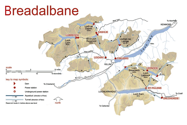
The sizes of the power stations in the scheme are as follows.
- Lubreoch – 4 MW
- Cashlie – 11 MW
- Lochay – 45 MW
- Finlarig – 16.5 MW
- Lednock – 3 MW
- St Fillans – 16.8 MW
- Dalchonzie – 4 MW
This gives a total power of 100.3 MW.
This Google Map shows Loch Tay.
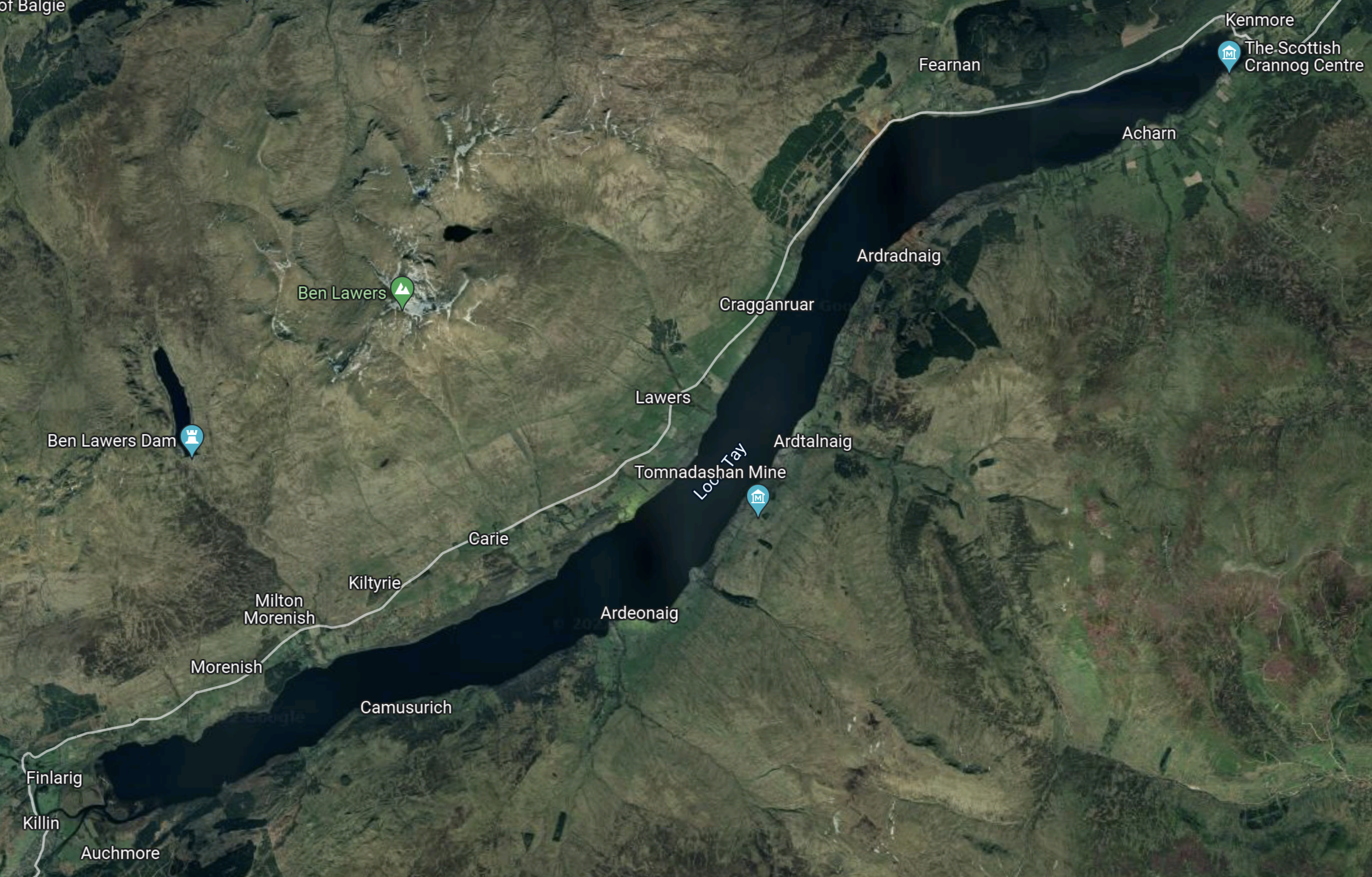
Note
- Finlarig. where there is a power station, with a capacity of 16.5 MW.
- Ben Lawers dam, is to the West of Ben Lawers and is marked by a blue arrow.
- The biggest power station in the scheme is Lochay power station, which has a capacity of 45 MW.
- Lochay power station is to the West of Finlarig power station and both appear to be fed from Ben Lawers dam and others to the North.
This Google Map shows Loch Earn.
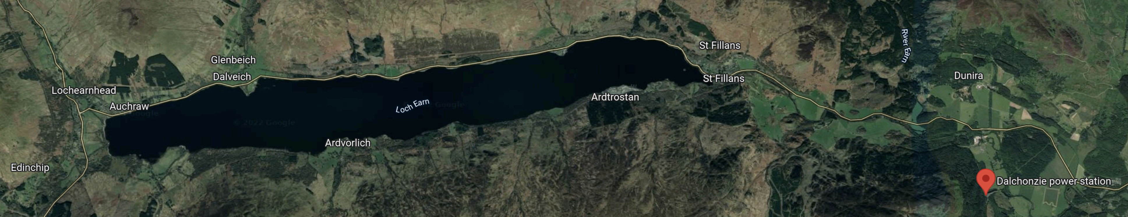
Note.
- Loch Earn is South of Loch Tay
- The red arrow indicates Dalchonzie power station.
- Dalchonzie power station has a generating capacity of only 4 MW.
This Google Map shows the location of Loch Lednoch between Loch Tay and Loch Earn.
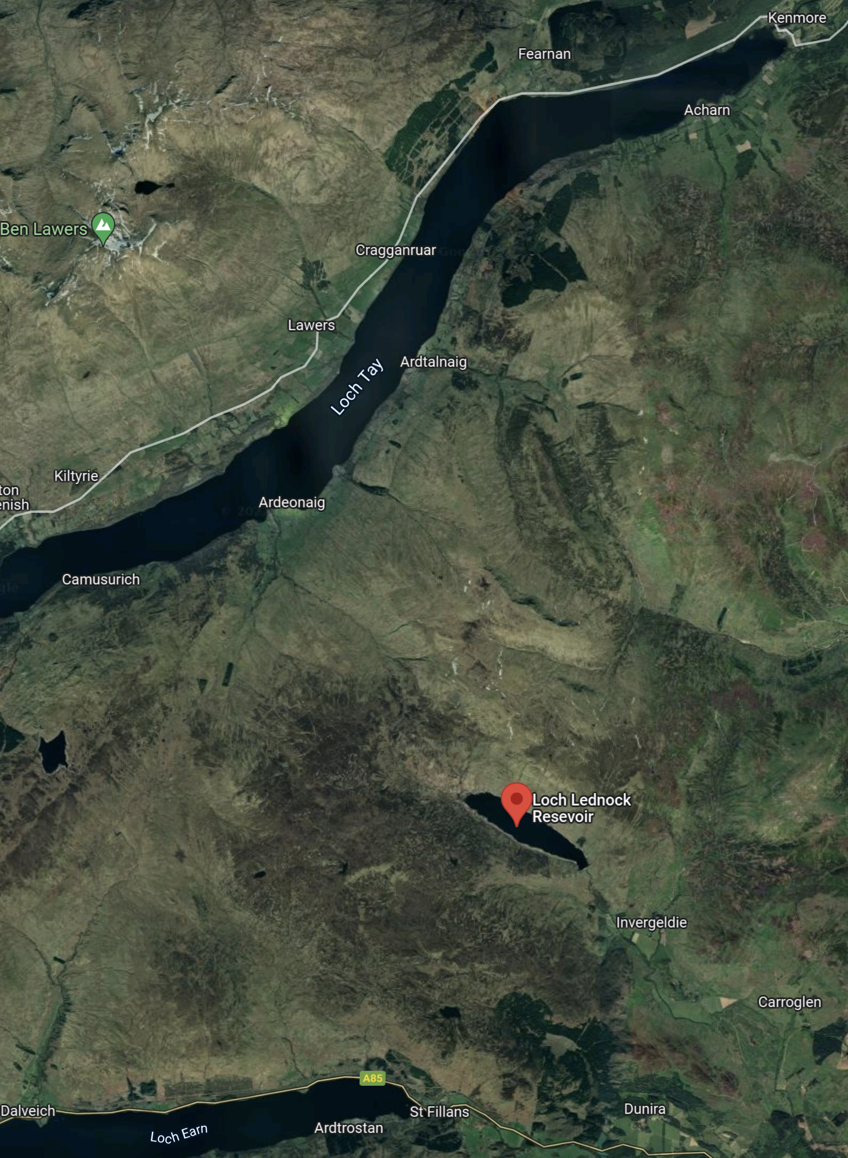
Note that Lednoch has the 3 MW Lednoch power station at its Northern end.
This map shows to the West of Ben Lawers.
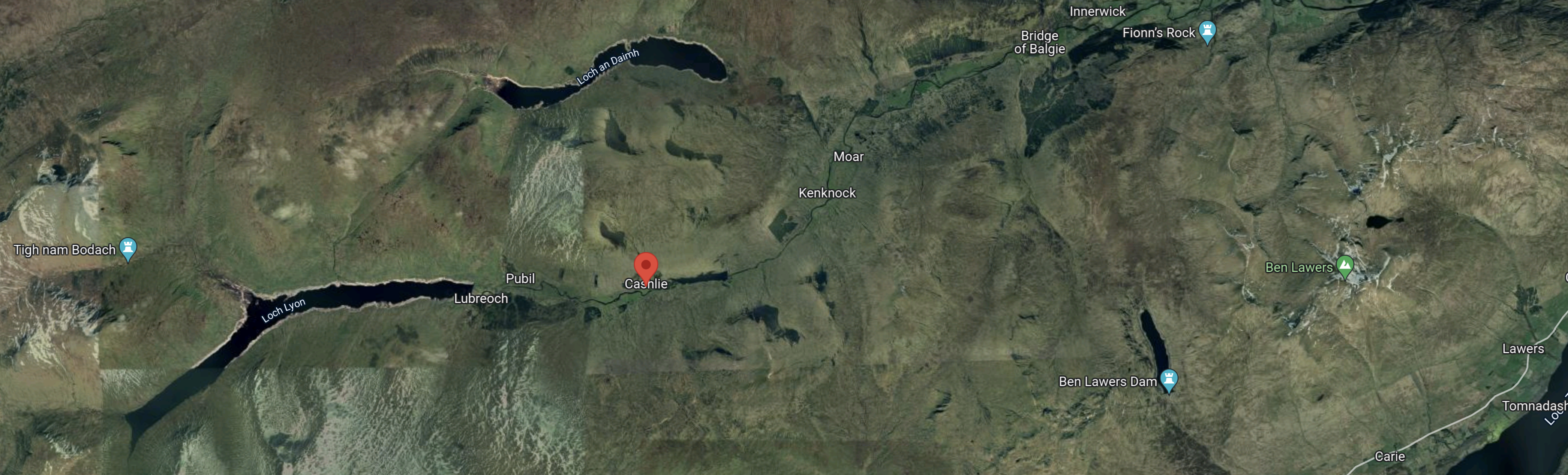
The red arrow indicate the rough location of the 11 MW Cashlie power station.
Is The Breadalbane Scheme Complete?
Looking at the dates of power station construction, I wonder if the dam builders concentrated in the early 1960s on the construction of Cruachan pumped storage station, which was constructed between 1959 and 1965.
Also to me, the Breadalbane scheme seems to have a lot of power stations and tunnels for just over 100 MW.
- At Rannoch, there is a 44 MW power station on the shores of Loch Rannoch, that was built in 1930.
- At Sloy there is a 152.5 MW power station on the shores of Loch Lomond, that was built in 1950.
I would have thought that a progression from Sloy, would have seen a large power station built on the shores of Loch Tay, whereas Lochay power station is only 44 MW.
This Google Map shows Lochan Breaclaich, which is a lake created by the construction of Breaclaich dam.
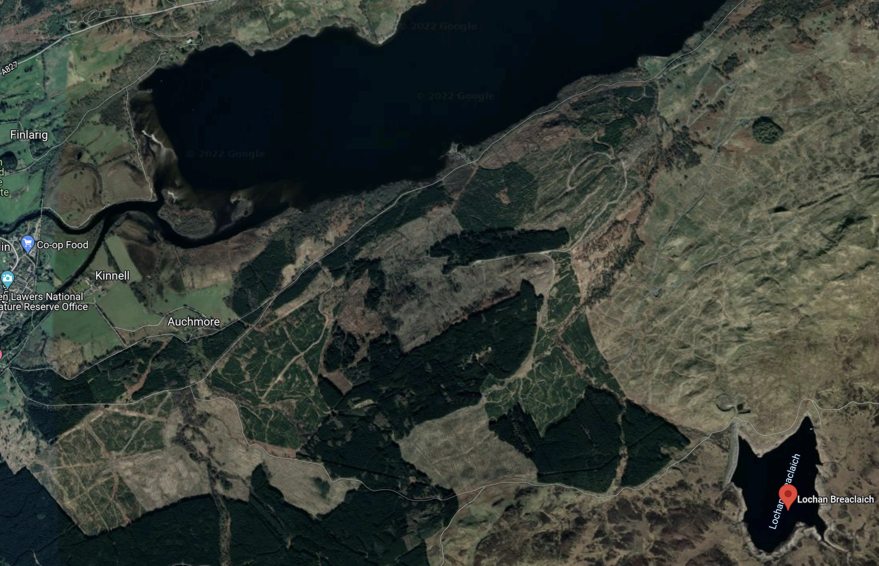
Lochan Breaclaich is marked by the red arrow and it is Loch Tay at the top of the map.
This page on the Canmore web site gives these details of Lochan Breaclaich and its dam.
Breaclaich dam is designed to prevent Loch Breachlaich and a number of other intakes from discharging into the Loch Tay catchment. A tunnel intake gatehouse is upstream of the dam and takes water via tunnel and pipeway through to Lednock power station.
The SSE map shows this tunnel to the North-Western end of Loch Lednoch, where the Lednoch power station is located.
It seems a lot of work was done to feed the power station, which has a capacity of just 3 MW.
Was it originally intended that Lochan Breaclaich would have fed a large power station on the Southern shore of Loch Tay?
Strathclyde University And Pumped Storage Power For Scotland
This page on the Strathclyde University gives a list of the pumped storage potential for Scottish hydrogen-electric dams and power stations.
These figures are given for the dams and lochs in the Breadalbane scheme.
- Ben Lawers – 12 GWh
It would appear that based on research from Strathclyde University, that the Breadalbane scheme could support 12 GWh of pumped storage.
Could this be augmented by a pumped-storage scheme from the Southern shore of Loch Tay to Lochan Breaclaich?
- Lochan Breaclaich is at an altitude of 443 metres.
- Loch Tay is at an altitude of 106 metres.
- Foyers pumped storage has a capacity of 300 MW and a head of 179 metres.
If a 12 GWh pumped storage system can be built on the North side of Loch Tay, I can’t see why with a head of 337 metres, one can’t be built on the South side of the Loch.
Was this the original plan?
Water Flows In The Breadalbane Scheme
Looking at the SSE Renewables map of the Great Glen scheme, water flows appear to be as follows.
- Loch an Daimh to Stronuich Reservoir via Cashlie power station
- Loch Lyon to Stronuich Reservoir via Lubreoch power station
- Stronuich Reservoir to Lochay power station
- Loch Ben Lawers to Finlarig power station
- Lochan Breaclaich to Loch Lednock via Lednoch power station
- Loch Lednock to Loch Earn via St. Fillans power station
- Loch Earn to Dalchonzie power station
It seems to be an expensive scheme with lots of tunnels and an underground power station at St. Fillans.
Refurbishing And Repurposing The Breadalbane Scheme
Perhaps as the power stations are now over fifty years old, one simple way to increase the generating capacity of the Breadalbane scheme, might be to selectively replace the turbines, with modern turbines, that can generate electricity more efficiently.
I suspect that SSE Renewables have an ongoing program of improvements and replacements for all of their hydro-electric stations in Scotland. Some turbines at Sloy power station have already been replaced with larger ones.
Adding Pumped Storage To The Breadalbane Scheme
In this list of Scotland’s lochs on Wikipedia, there is a short list of the largest and deepest lochs.
- The first five are Loch Ness, Loch Lomond, Loch Morar, Loch Tay and Loch Awe.
- Loch Ness has the Foyers pumped-storage scheme and others are in development.
- Loch Awe has the Cruachan pumped-storage scheme.
- Loch Lomond has the Sloy pumped-storage scheme in development.
- Loch Morar is used in the Lochaber hydro-electric scheme.
It seems to me, that Loch Tay could support some pumped-storage, just because of its size.
Strathclyde University have identified that Ben Lawers can support 12 GWh on the North side of Loch Tay.
Could a scheme involving Lochan Breaclaich add a similar amount of pumped-storage on the South side of Loch Tay?
I also suspect there are possibilities for adding pumped-storage to and from Stronuich Reservoir.
Conclusion
I believe that Breadalbane is an incomplete scheme and that pumped-storage could convert this scheme into a much more powerful and larger scheme.
There would appear to be two schemes, that could each add around 12 GWh of pumped storage.
One advantage is that the waters of Loch Tay can be used for the lower reservoir.
Shin Hydro Power Scheme
The Shin hydro-electric scheme was built in the 1930s and 1950s, by the North of Scotland Hydroelectric Board.
- The scheme is now owned by SSE Renewables and has a page on their web site.
- There are three individual power stations; Casseley, Lairg and Shin.
- There are two dams
This map from the SSE Renewables web site shows the layout of the dams and power stations.
The sizes of the power stations in the scheme are as follows.
- Casseley – 10 MW
- Lairg – 3.5 MW
- Shin – 18.6 MW
This gives a total power of 32.1 MW.
This Google Map shows the same area as the SSE Renewables Map.
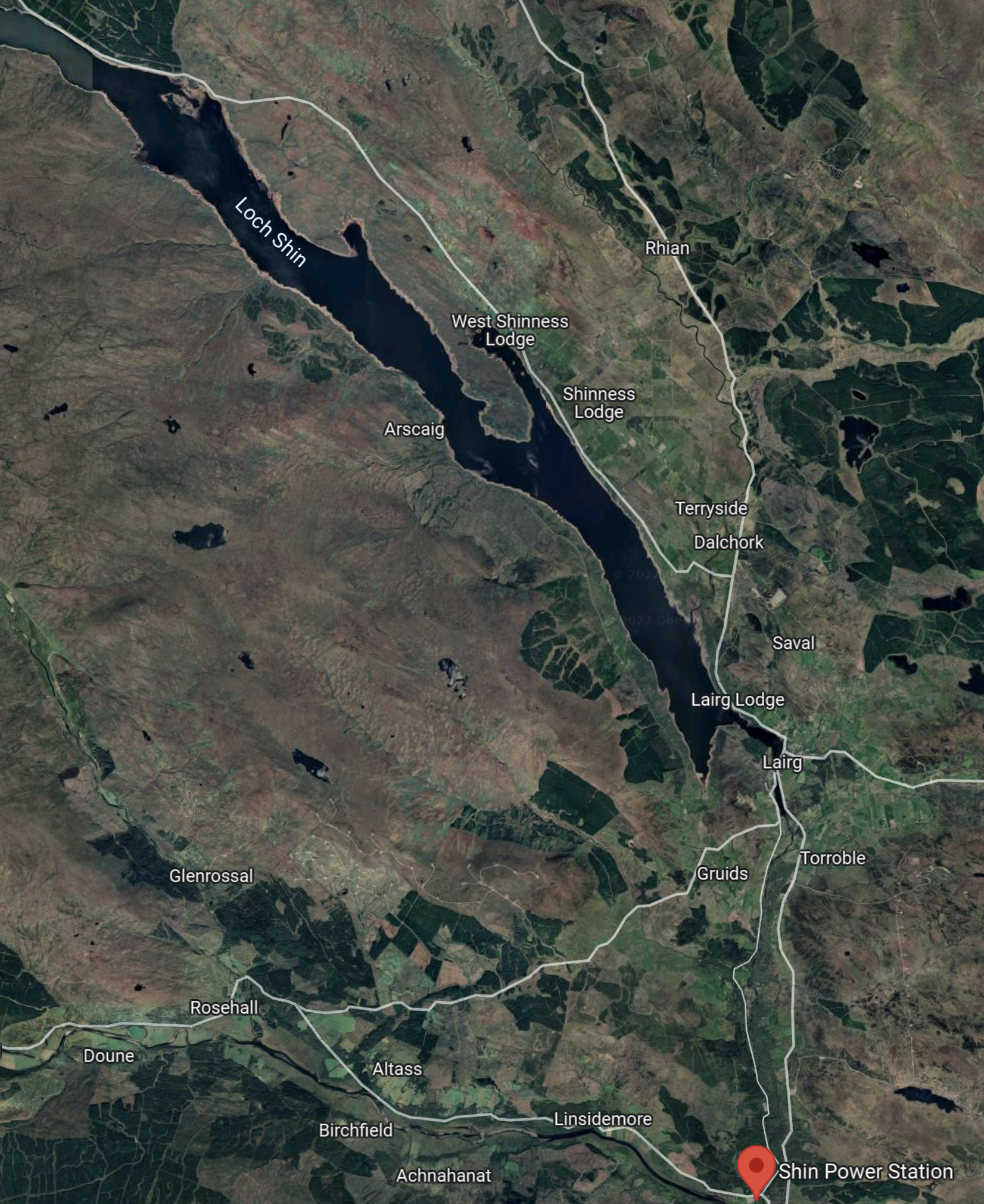
Note.
- Shin power station is in the South-West corner of the map.
- Loch Shin is the large area of water in the top half of the map.
- The village of Lairg is at the South end of Loch Shin.
This Google Map sows Shin power station in detail.
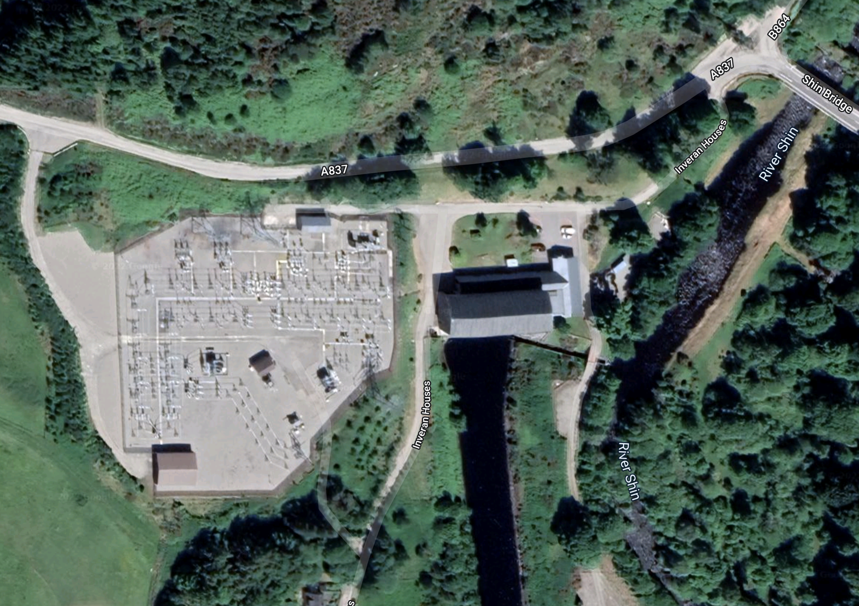
Note.
There is a large substation on the left side of the map.
Shin power station is the building straddling the water to the right of the substation.
I have found this informative press release on the SSE web site, which is entitled £5 m Investment In Shin Hydro Station.
These are a couple of paragraphs.
John McDonald, Hydro Manager for SSE said: “This is the first major overhaul of Shin Hydro Station in its 55-year history – a true testament to the reliability and longevity of hydro-electric power.
“There are few other industries that could claim to be making the same product with the same machines and same specifications as they were in the 1950s. This overhaul will mean that Shin will be producing clean, green electricity for decades to come.”
Surely, that is an argument for more hydro schemes.
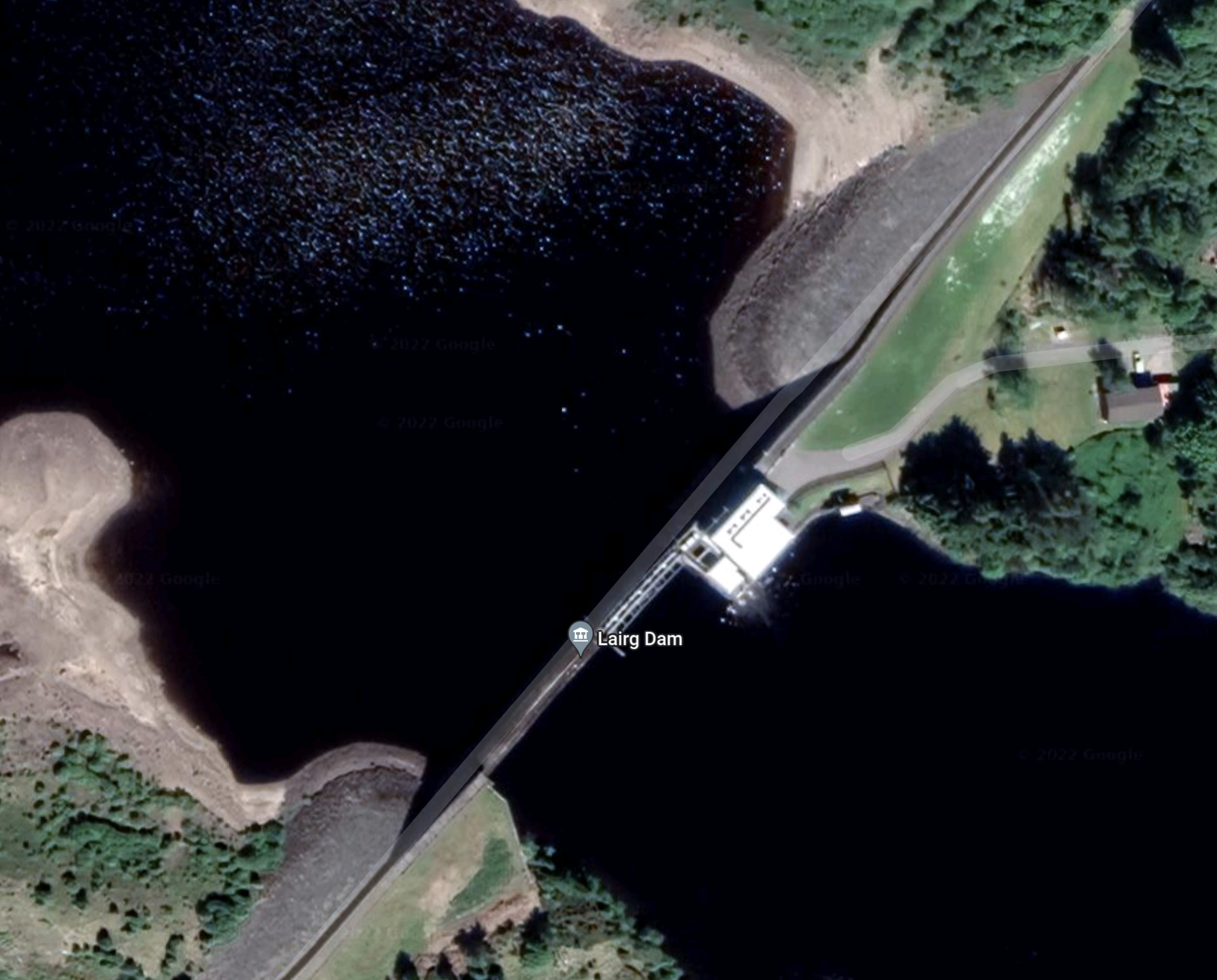
This Google Map shows Lairg.
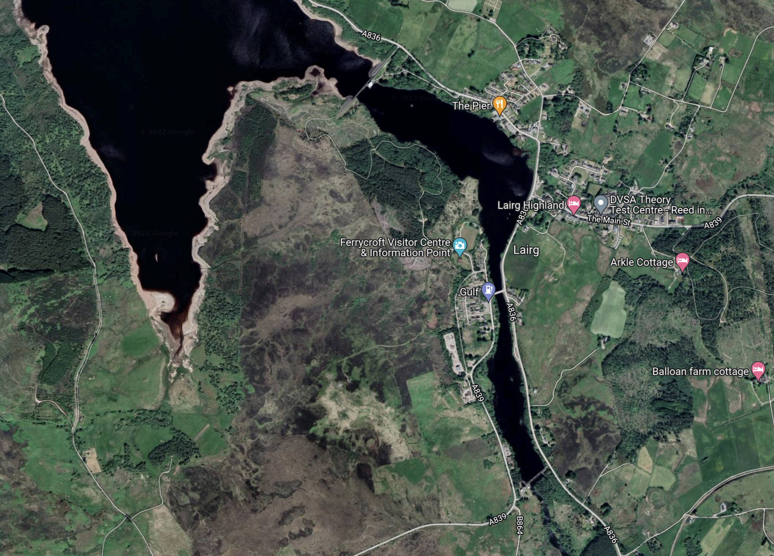
Note that there are two dams and a bridge across Loch Shin/River Shin.
This Google Map shows dam at the Southern end of the Loch.
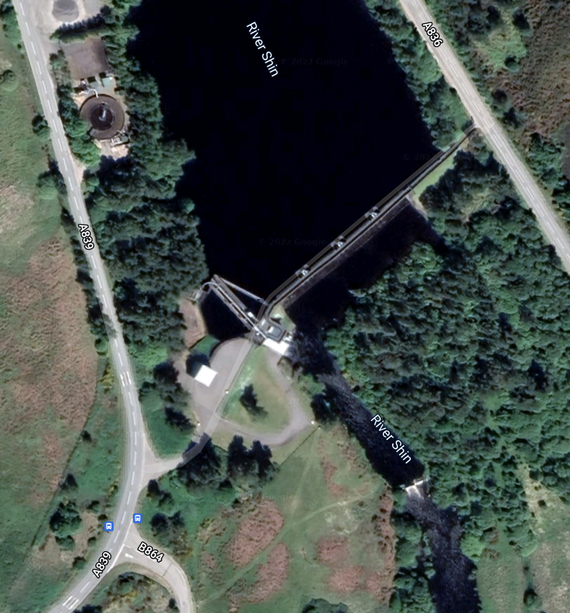
This Google Map shows Lairg dam and power station at the Northern end of the village.
It would appear to be a much simpler scheme, than others I have examined.
Conclusion
I would be very surprised if any pumped storage were to be added to this scheme.
The Coire Glas Pumped Storage Scheme
The Coire Glas pumped storage scheme, which is being developed by SSE Renewables will be the first large scale pumped storage scheme to be developed in the UK for more than 30 years.
- It would have a power output of 1.5 GW.
- Compared to Dinorwig (Electric Mountain) in Wales at 9.1 GWh and Cruachan in Scotland at 7.1 GWh, it will be a giant.
- Planning permission has been obtained.
The Coire Glas project has a web site.
This is the introductory paragraph.
Coire Glas is a hydro pumped storage scheme with a potential capacity of up to 1500MW. Coire Glas is an excellent pumped storage site with a large lower reservoir (Loch Lochy) and a significant elevation of more than 500m between the lower and the new upper reservoir site over a relatively short distance.
There is also an explanatory video.
This map was clipped from this SSE planning document.
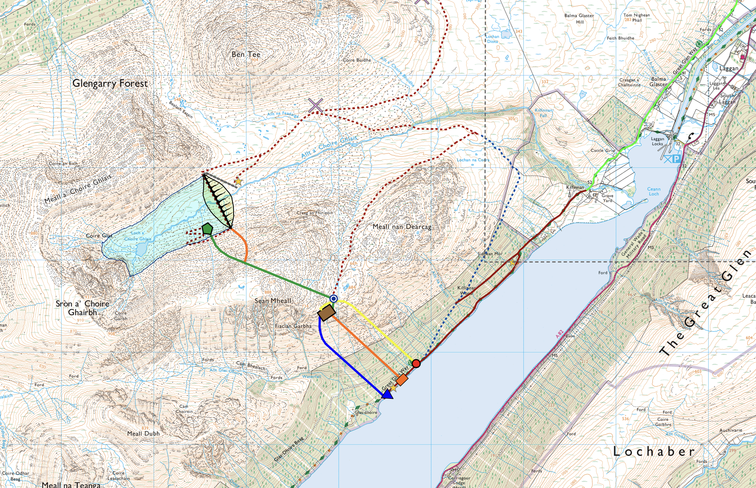
Note.
- Loch Lochy in the Great Glen will be the lower reservoir.
- Loch Lochy is a freshwater loch, that is up to seventy metres deep.
- The top reservoir is formed by building a dam across the stream, that runs into the Northern end of Loch Lochy.
- The green line leading from the pentagon in the lake behind the dam towards Loch Lochy is the headrace tunnel.
- It leads to the brown rectangle, which is the underground power station.
- The blue line leading from the power station, where water is discharged into the loch.
- The two orange lines are access tunnels.
- The yellow line is the emergency access tunnel.
It is a standard layout for a pumped storage power station.
- To store electricity, water is pumped from Loch Lochy and stored in the new lake.
- To generate electricity, water runs down the headrace tunnel, through the turbines and then down the tailrace into Loch Lochy.
- The power station would have a number of pump/turbines, that can do both tasks.
In addition, any water from rain or snow melt, that runs into the top lake gives low-cost extra electricity.
This layout of the dam and the upper lake was clipped from this SSE planning document.
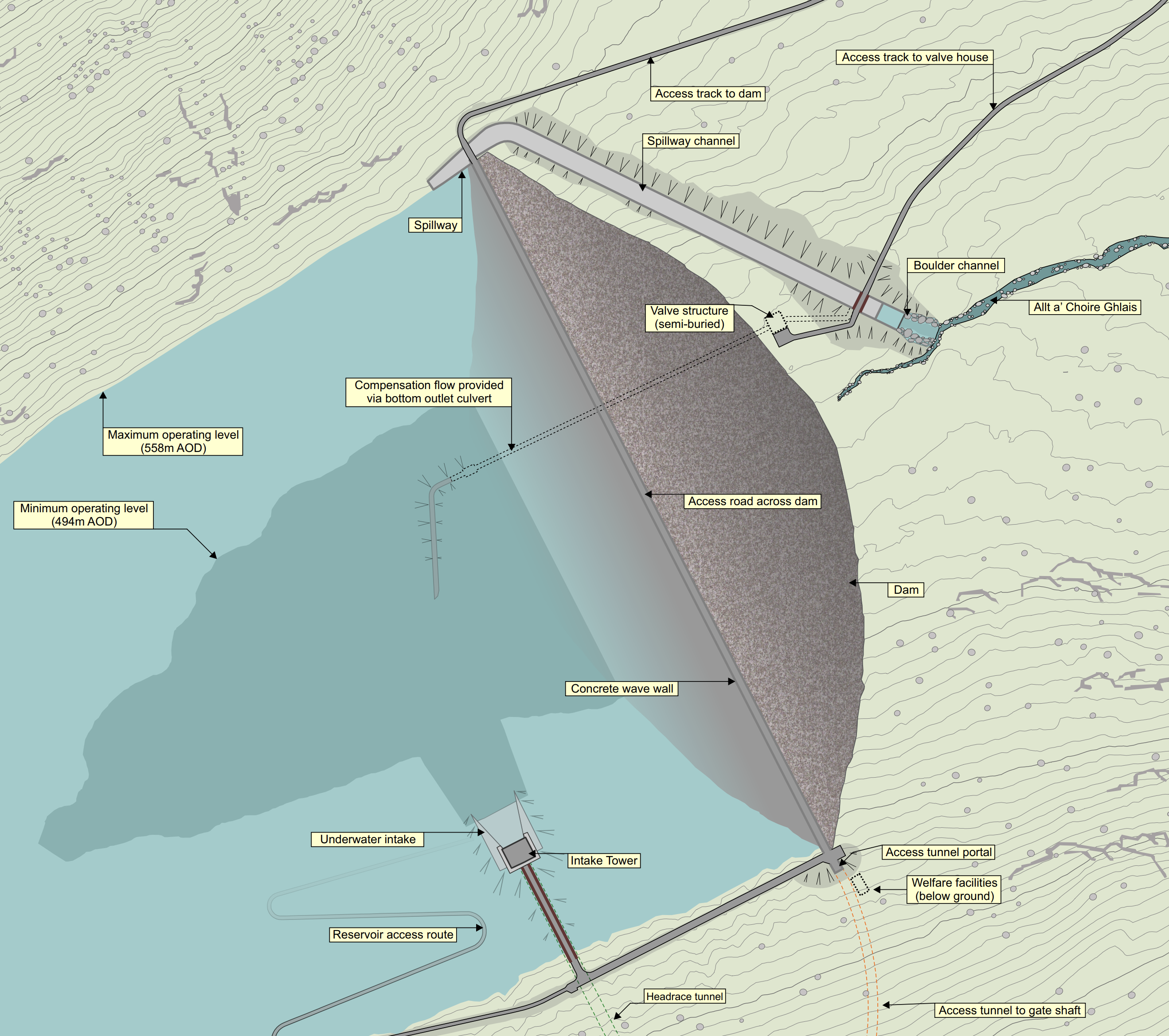
It would be an impressive structure.
Could this pumped storage scheme give the UK energy security?
Repurposing The Tummel Hydro-Electric Scheme
The Tummel hydro-electric scheme was built in the 1930s and 1950s, by the North of Scotland Hydroelectric Board.
- The scheme is now owned by SSE Renewables and has a page on their web site.
- There are nine individual power stations; Gaur, Cuaich, Loch Ericht, Rannoch, Tummel, Errochty, Trinafour, Clunie and Pitlochry.
- There are four dams; Gaur, Errochty, Clunie and Pitlochry.
This map from the SSE Renewables web site shows the layout of the dams and power stations.
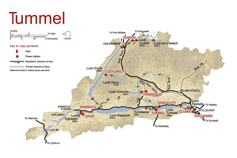
This description of the scheme is from Wikipedia.
The Tummel hydro-electric power scheme is an interconnected network of dams, power stations, aqueducts and electric power transmission in the Grampian Mountains of Scotland. Roughly bounded by Dalwhinnie in the north, Rannoch Moor in the west and Pitlochry in the east it comprises a water catchment area of around 1,800 square kilometres (690 sq mi)[1] and primary water storage at Loch Ericht, Loch Errochty, Loch Rannoch and Loch Tummel, in Perth and Kinross. Water, depending on where it originates and the path it takes, may pass through as many as five of the schemes nine power stations as it progresses from north-west to south-east. The scheme was constructed in the 1940s and 50s incorporating some earlier sites.
Note.
- There are no underground power stations.
- The scheme is what is known as a run-of-the-river hydroelectric scheme.
The sizes of the power stations in the scheme are as follows.
- Gaur – 75 MW
- Cuaich – 2.5 MW
- Loch Ericht- 2.2 MW
- Rannoch – 44 MW
- Tummel – 34 MW
- Errochty – 75 MW
- Trinafour – 0.5 MW
- Clunie – 61 MW
- Pitlochry – 15 MW
This gives a total power of 309.2 MW.
This Google Map shows the same area as the SSE Renewables Map.
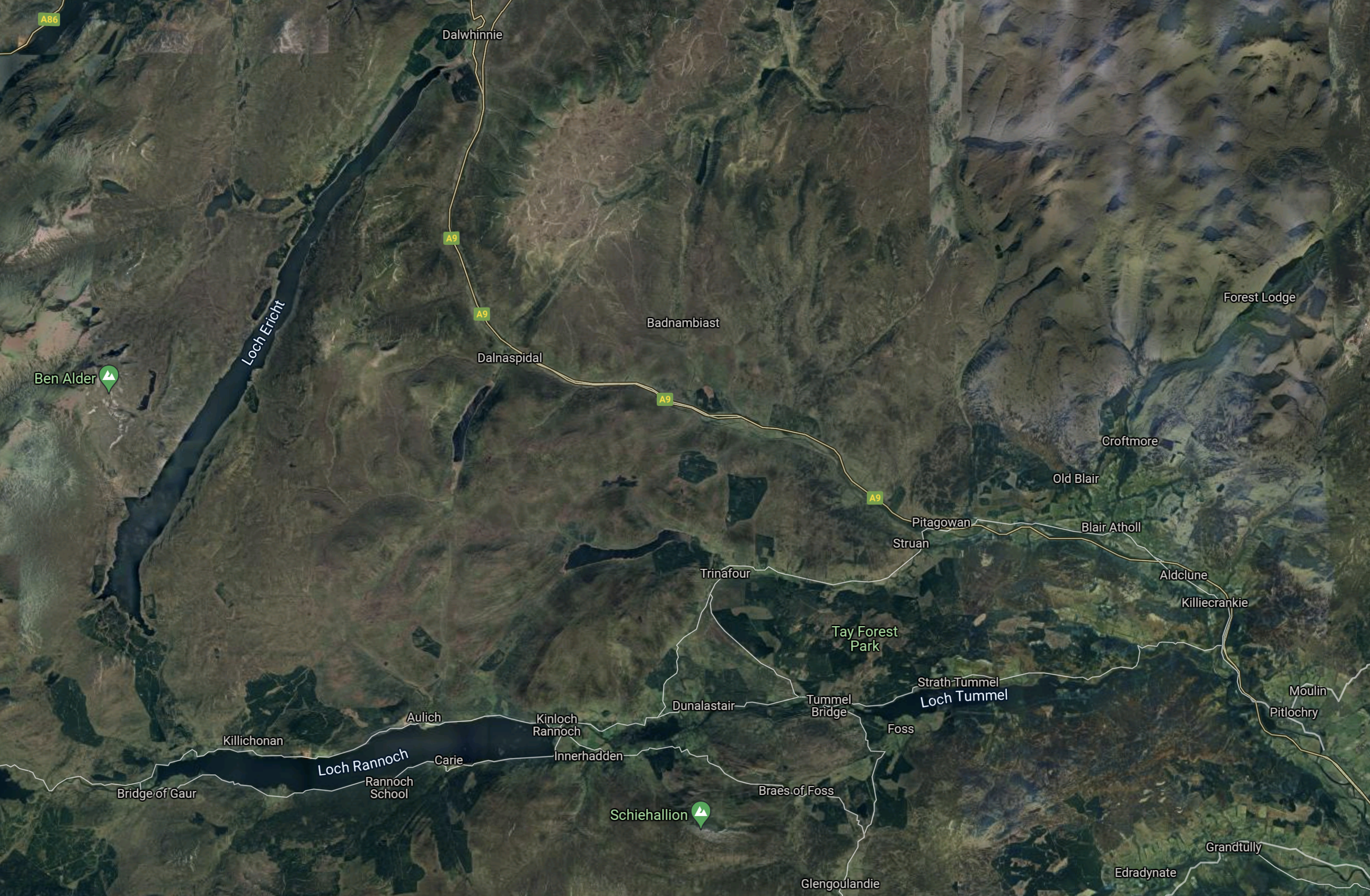
Note.
- Dalwhinnie is at the North of the map.
- Gaur is in the South-West corner of the map.
- Pitlochry is in the South-East corner of the map.
There are no underground power stations.
Strathclyde University And Pumped Storage Power For Scotland
This page on the Strathclyde University gives a list of the pumped storage potential for Scottish hydrogen-electric dams and power stations.
These figures are given for the dams and lochs in the Tummel scheme.
- Errochty – 16 GWh
- Clunie – 40 GWh
- Rannoch – 41 GWh
- Tummel – 38 GWh
It would appear that based on research from Strathclyde University, that the Tummel scheme could support over 120 GWh of pumped storage.
Water Flows In The Tummel Scheme
Looking at the SSE Renewables map of the Tummel scheme and reading this section in the Wikipedia entry for the Tummel scheme, which is entitled Water Route, water flows appear to be as follows.
- Loch an t-Seilich to Loch Cuaich
- Loch Cuaich to Loch Ericht via Cuaich power station and the Cuaich aqueduct
- Loch Garry to Loch Ericht via Ericht power station.
- Loch Ericht to Loch Rannoch
- Loch Eigheach to Loch Rannoch via Gaur power station
- Loch Rannoch to Dunalastair Water via Kinloch Rannoch weir
- Dunalistair Water to Loch Tummel via Tummel power station
- River Bruar and River Garry to Loch Errochty
- Loch Errochty to Loch Tummel via Errochty power station
- Loch Errochty to Trinafour power station
- Loch Tummel to Loch Faskally via Clunie power station
- Loch Faskally to Pitlochy power station
Note.
Water from Loch an t-Seilich can take various routes to Clunie and Pitlochry power stations.
Water from Loch Eigheach goes through Loch Rannoch, Dunalistair Water and Loch Tummel to Clunie and Pitlochry power stations.
It seems a complicated scheme but it does have a capacity of 307 MW, which compares with 389 MW of Bankside power station.
Refurbishing And Repurposing The Tummel Scheme
Perhaps as the power stations are now over fifty years old, one simple way to increase the generating capacity of the Affric/Beauly scheme might be to selectively replace the turbines, with modern turbines, that can generate electricity more efficiently.
I suspect that SSE Renewables have an ongoing program of improvements and replacements for all of their hydro-electric stations in Scotland. Some turbines at Sloy power station have already been replaced with larger ones.
In The Affric/Beauly Hydro-Electric Scheme, I wrote about the control system needs of that scheme, which I felt could be fairly challenging.
I suspect the control of the Tummel scheme is equally challenging.
Adding Pumped Storage To The Tummel Scheme
I’ll look at each possibility in turn.
Loch Errochty
Strathclyde University estimated that 16 GWh of pumped storage could be added to Loch Errochty.
This Google Map shows the Eastern end of Loch Errochty.
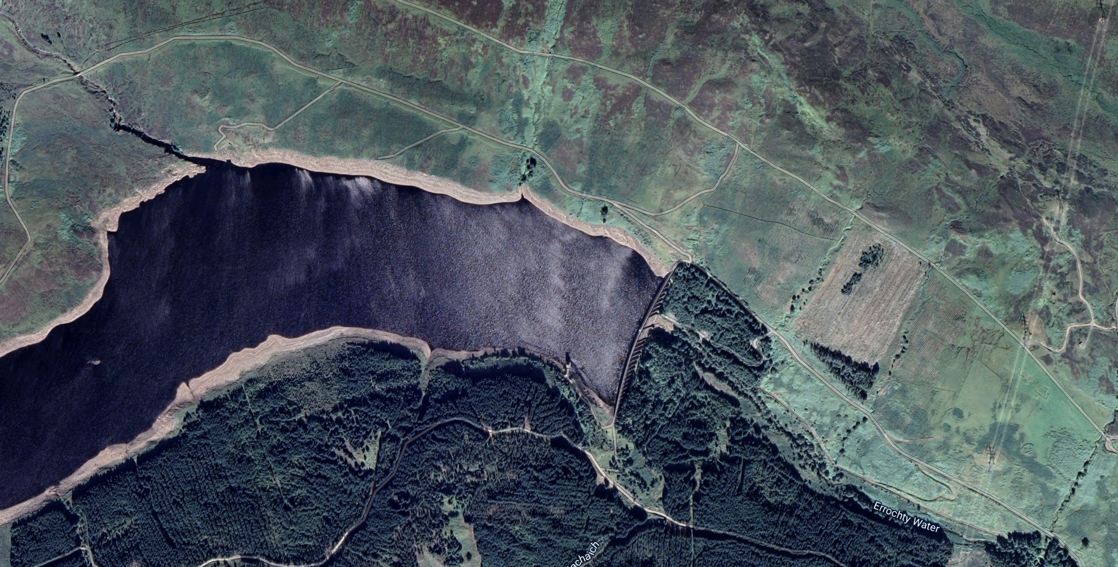
Note the dam at the Eastern end of the loch.
- The dam is 354 metres long by 49 metres high.
- The dam was built in 1957 and the lake is man-made.
- The loch stands at 330 metres above sea level.
- Water flows from the loch to the Errochty power station at the Western end of Loch Tummel, through a ten kilometre long tunnel.
This Google Map shows Errochty power station and Loch Tummel.
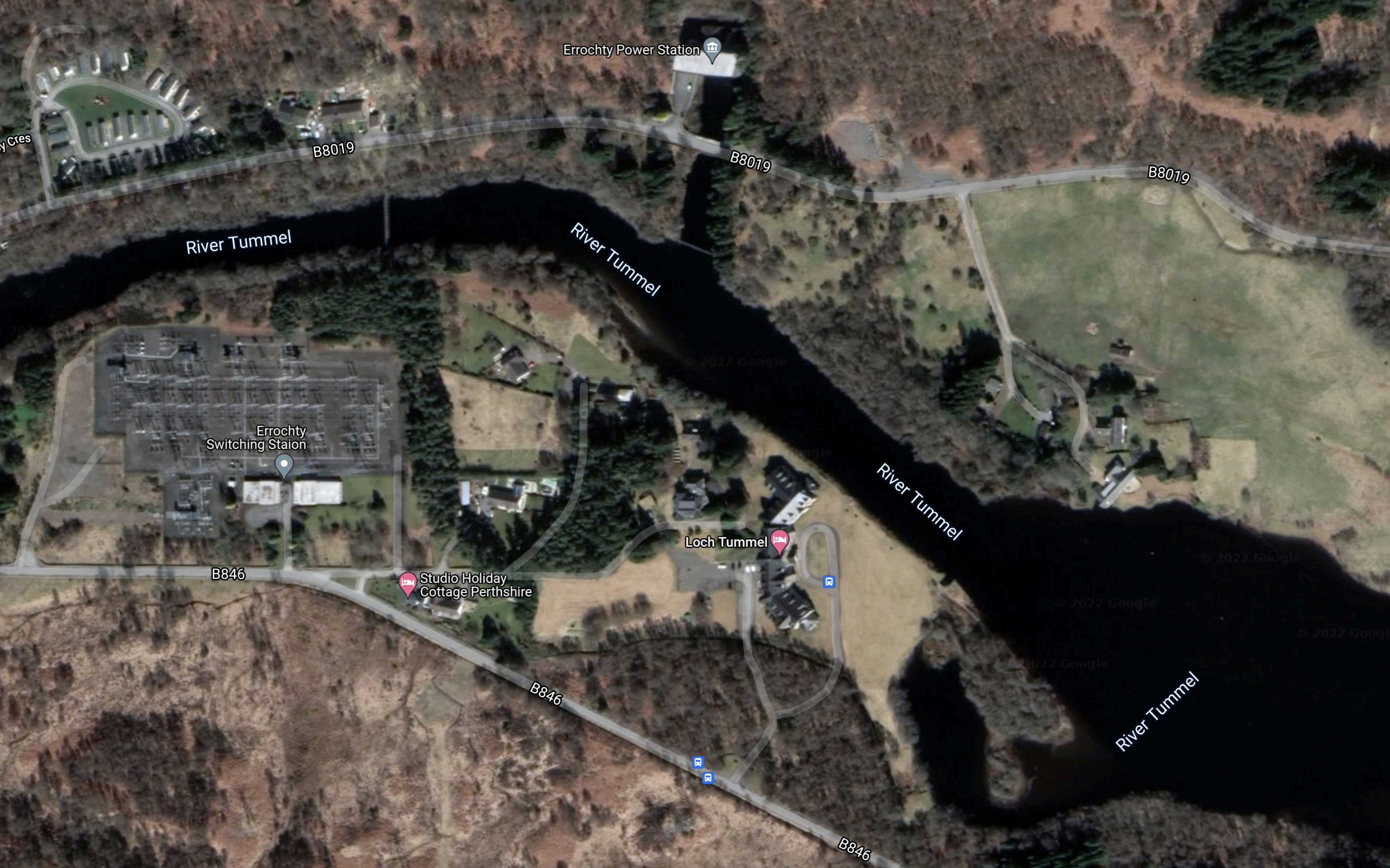
Note.
- Errochty power station is at the top of the map in the middle on the channel connecting it to the River Tummel.
- Errochty power station has two turbines and a maximum output of 75 MW.
- There is what appears to be a large switching station at the Western side of the map.
I obviously don’t know for sure, but I suspect this could be an easier scheme to convert, if the current turbines could be replaced with pump/turbines.
There is a section with the title; Water Supply To The Loch in the Wikipedia entry for Loch Errochty, where this is said.
Loch Errochty’s main feeder streams are the Allt Sléibh and the Allt Ruighe nan Saorach which both rise in the high ground to the west of the head of the loch. Other small streams flow directly off the 892-metre-high (2,927 ft) mountain of Beinn a’ Chuallaich which stands just to the south. Supplementary water is diverted into the loch from the east by the Errochty catchwater, a system of tunnels and surface pipelines at a height of approximately 380 metres which redirects water from five small tributary streams of the River Garry, and the Garry itself. The catchwater then goes through a tunnel in the hill which separates the Garry and Errochty valleys to join the loch. This method of re-directing water allows it to be used more often to generate electricity. Some of the water within the Tummel scheme passes through five of the power stations and thus generates electricity five times.
That strikes me as being very sophisticated for the 1950s and if the engineering and tunnels are up to a high standard, it might be that conversion of this power station to a 75 MW power station with 16 GWh pumped storage is a distinct possibility.
It might even be possible to increase the generating capacity of the power station.
Clunie
Strathclyde University estimated that 40 GWh of pumped storage could be added above Clunie power station.
This Google Map shows the River Tummel between Clunie and Pitlochry power stations.
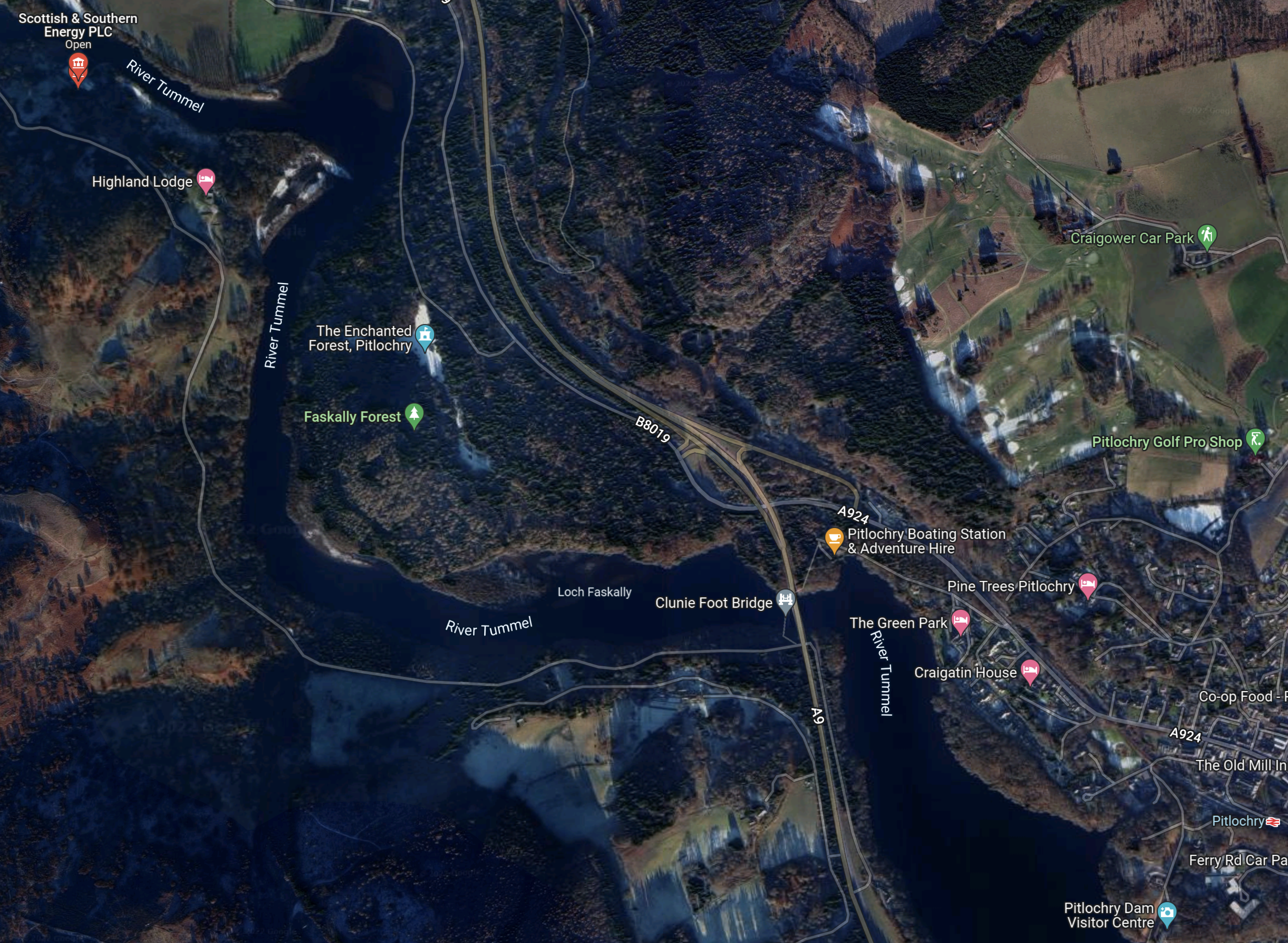
Note.
- Clunie dam and power station is marked by a red arrow labelled Scottish and Southern Energy in the North-West corner of the map.
- Pitlochry Dam and power station are in the South-East corner of the map.
- River Tummel and Loch Faskally link the two dams.
There is a large volume of water between the two dams.
In a pump-back hydro-electric water is pumped back from the lake below the dam into the reservoir above the dam. Such a system was added to the Grand Coulee Dam in the United States to increase its generating and storage capacity.
This Google Map shows how the water to the West of Clunie dam and power station stretches to the other end of Loch Tummel.
As there would be large volumes on both sides of the dam, I am fairly sure, that a pump-back system could be employed at Clunie power station.
Whether 40 GWh of storage could be added, would be one for the designers of the rebuilt dam and power station?
Tummel
Strathclyde University estimated that 38 GWh of pumped storage could be added above Tummel power station.
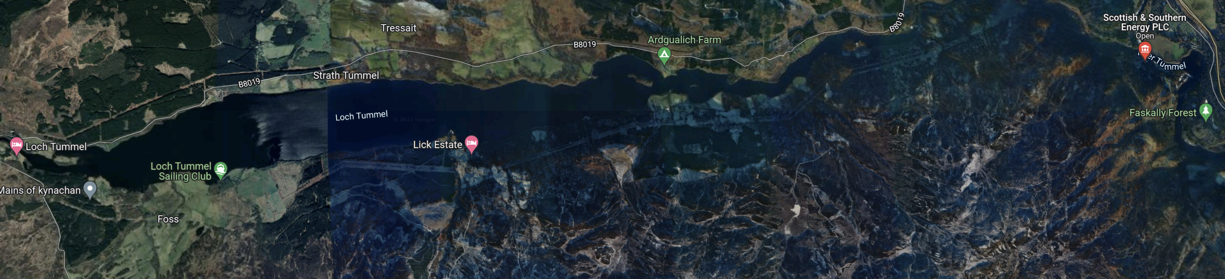
This Google Map shows the Eastern end of Loch Rannoch, Dunalastair Water, the River Tummel and Tummel power station.
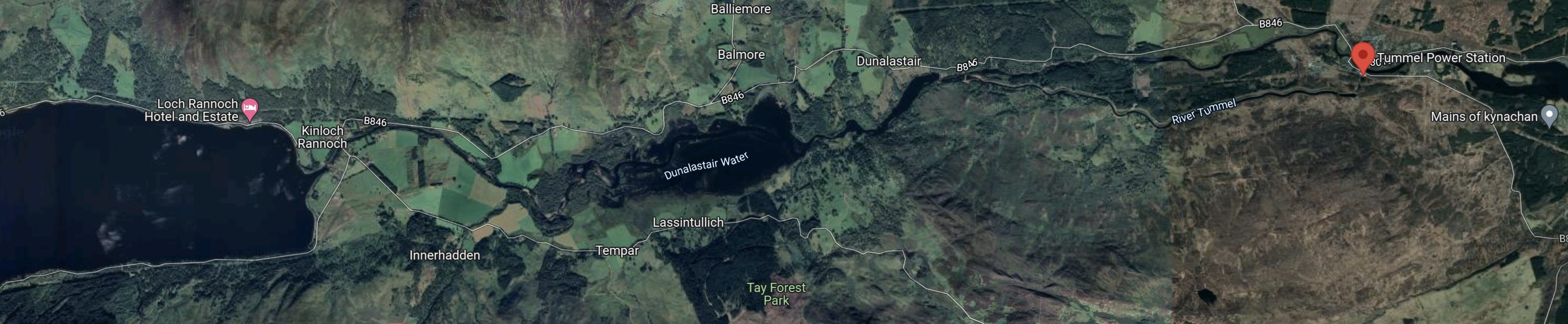
Note.
- Loch Rannoch is at the Western end of the map.
- Dunalastair Water is the smaller lake in the middle.
- Tummel power station is indicated by the red arrow at the East of the map.
This Google Map shows Tummel power station.
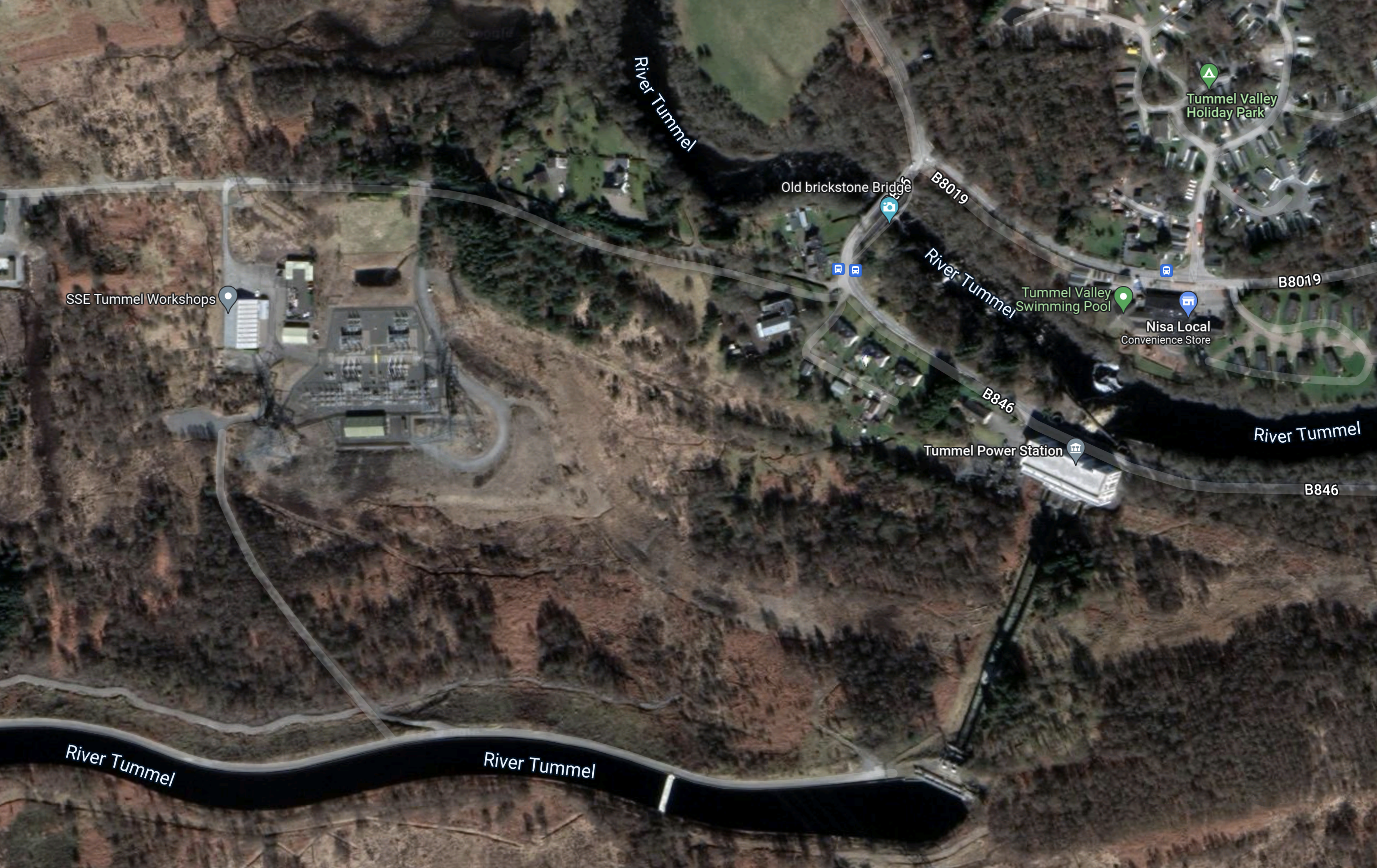
Note.
There appears to be two branches of the River Tummel.
- At the bottom of the map, it appears to be in an aqueduct and above the power station.
- Running across the top-right corner of the map, the second branch appears to be a low-level branch of the river.
- The height difference will mean that power station works well and generates its full 34 MW.
As with Clunie power station, I am sure there is scope for Tummel power station to pump water from Loch Tummel to Dunalastair water, when there is a surplus of wind-generated electricity.
But could space be found above Tummel power station to store enough water to create a massive 38 GWh pumped-storage power station?
Rannoch
This description of Lord Rannoch is from Wikipedia.
It is over 15 kilometres (9.3 mi) long in a west–east direction with an average width of about 1.2 kilometres (0.75 mi), and is deepest at its eastern end, reaching a depth of 130 metres (440 ft).
The loch could hold almost a half a billion tonnes of water.
This Google Map shows Loch Rannoch and Loch Ericht
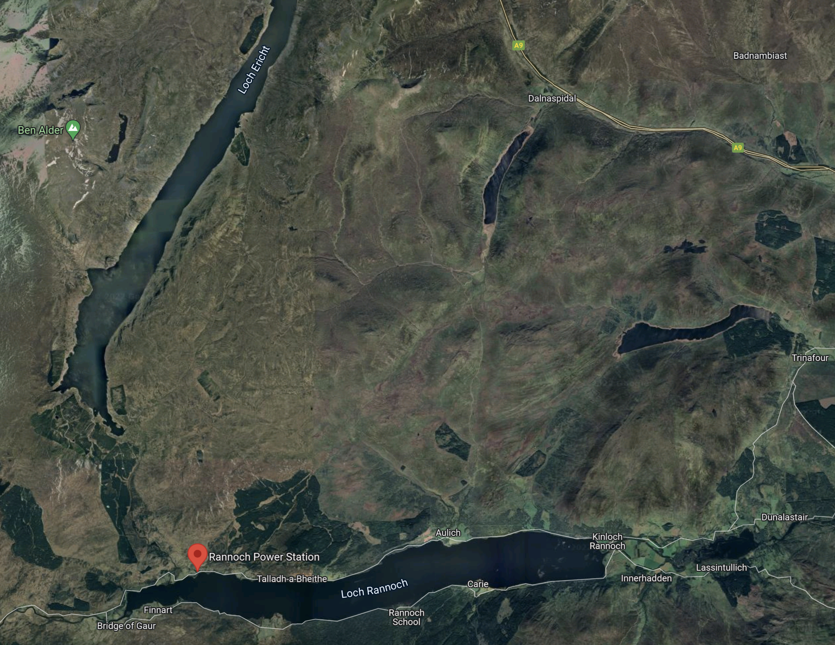
Note.
- Loch Rannoch is along the bottom of the map with Loch Dunalastair to the right.
- Loch Rannoch has an altitude of 205 metres.
- Rannoch power station is indicated by the red arrow.
- Rannoch power station was built in 1930 and the history of the power station is told in this page on the SSE web site, which is entitled A Real Gem In Hydro History.
- Loch Ericht runs to the North from above the power station.
- Loch Ericht has an altitude of 350 metres.
This Google Map shows Rannoch power station to a larger scale.
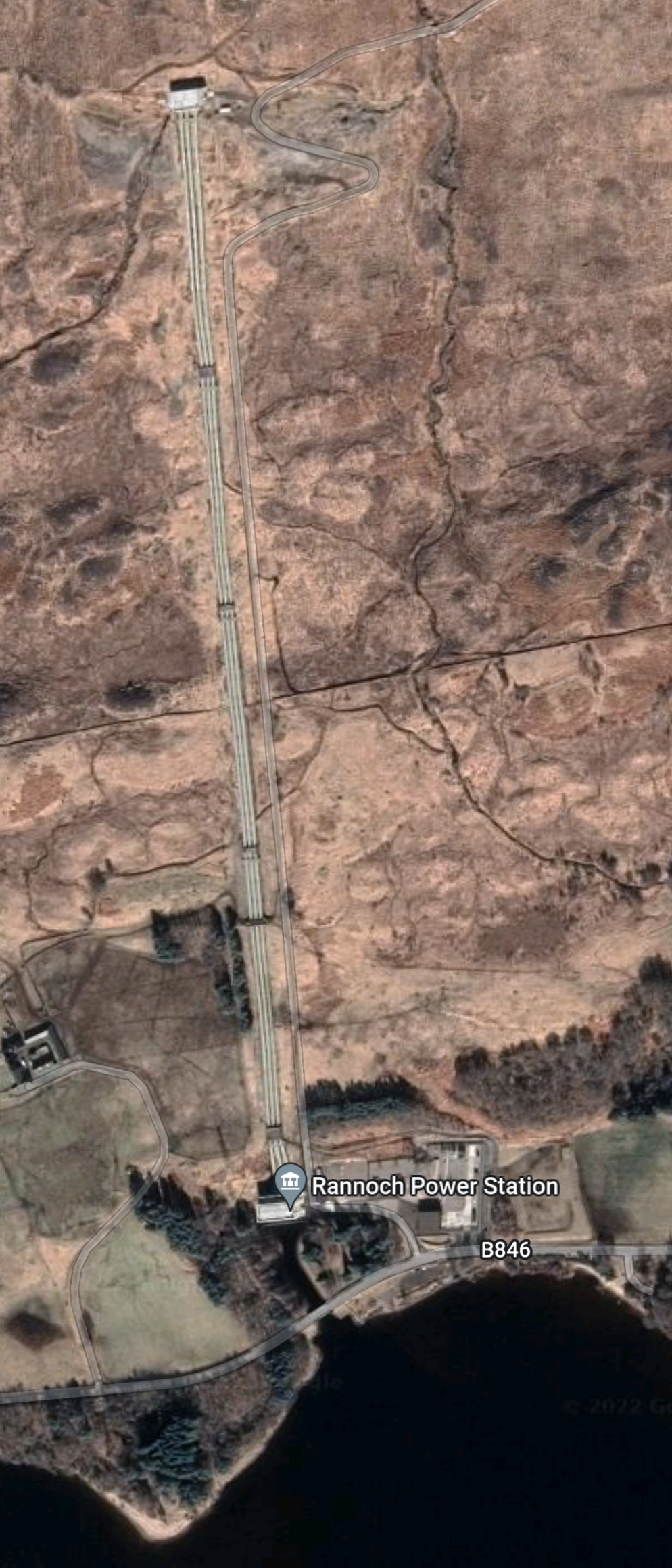
Rannoch power station is on the shore of Loch Rannoch and is described in this section in Wikipedia. This is said.
Rannoch Power Station, on the northern shore of the loch, is part of the Tummel hydro-electric power scheme, which is operated by SSE. The power station has a vertical head of 156 m (512 ft) and a total generating capacity of 44 MW, and uses water fed by pipeline and tunnel from Loch Ericht which is discharged into Loch Rannoch.
There are four pipes running down the hill from Loch Ericht, which deliver water to the power station.
The layout of Rannoch power station seems very similar to Sloy power station, which I described in A Lower-Cost Pumped Hydro Storage System.
- Both power stations sit on a large deep loch.
- Both have pipes to supply water going up the hill and then in a tunnel to a large loch over a hundred metres above the lower reservoir.
- Rannoch power station is a 44 MW power station built in 1930.
- Sloy power station is a 152.5 MW power station built in 1950.
SSE have been examining if a pumped-storage station could be added to Sloy power station.
Given the similarity of the layouts of the two stations, it could be that if it is possible to add pump storage to Sloy, that this could also be done at Rannoch.
Could 41 GWh be stored above Rannoch power station? I won’t say it is not possible.
Conclusion
Research at Strathclyde University gives these figures for possible storage capacity for these dams and lochs in the Tummel scheme.
- Errochty – 16 GWh
- Clunie – 40 GWh
- Rannoch – 41 GWh
- Tummel – 38 GWh
Adding these up gives a total of 135 GWh of stored energy for the Tummel scheme.
But that assumes every power station and dam is expanded to fit Strathclyde’s research.
SSE Renewables are currently calling for tenders for Coire Glas, as I wrote about in SSE Renewables Launches 1.5GW Coire Glas Construction Tender.
This was my conclusion in that post.
It looks to me, that it’s almost certain that Scotland will get a 1.5GW/30 GWh pumped-storage system at Coire Glas.
Coire Glas could supply slightly more power than Sizewell B nuclear power station for twenty hours.
Now that’s what I call backup!
But in the Tummel scheme, there could be three places, where a 30 GWh pumped-storage scheme could be developed and one where a 16 GWh scheme could be developed.
I would expect that a conservative figure of between 40-60 GWh of pumped-storage capacity could be added to the Tummel scheme.
