National Grid Energise World’s First T-Pylons
The title of this post, is the same as that of this press release from National Grid.
These are the four bullet points.
- Electricity is flowing to homes and businesses through the first new pylon design in the UK for nearly 100 years.
- Major milestone in National Grid’s Hinkley Connection project to connect 6 million homes and businesses in the South West to home grown, low carbon energy.
- The T-design, with a single pole and cross shaped arms, is around a third shorter than the traditional design with a smaller ground footprint.
- The T-pylons, along with a new substation and underground cabling, are now incorporated into National Grid’s electricity transmission network delivering electricity in Somerset and across England and Wales.
This is the first paragraph.
National Grid has successfully energised 36 of the world’s first T-pylons between Bridgwater and Loxton in Somerset. The new shaped pylons have been constructed as part of the £900 million Hinkley Connection Project, a new 57 km high-voltage electricity line that will connect six million homes and businesses to new sources of home grown, low carbon energy and help the UK to meet its net zero by 2050 target.
There is a video in the press release, which is well worth a view.
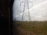
- The size of the pylons certainly reduces their visibility.
- It appears there are seven cables on either side.
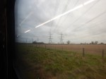
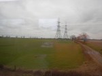
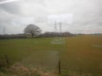
These pictures show the transmission lines to the Sizewell power station site.


Note.
- The lower height is very noticeable.
- There seem’s to be a lot more wires.
- I would assume, that the reduced number of components, reduces the cost of installation and maintenance.
The installation proved that even in the most mundane of applications, innovation can bring positive results.
The T-pylons are a design by Danish company; Bystrup.
This is the specification from their comprehensive web-page.
- Power – 2 x 400 kV
- Height – 35 metres / 114 feet
- Units/km – 3 (5 units/mile)
- Material – Hot-dip galvanised steel, painted
- Assembly – On-site and quick – less than 10 parts
- Installation – Simple monopile foundation
- Production possible anywhere in the world
- Developed – 2011-2014
They’ve also won several awards.
- 1st prize in int. competition for RIBA
- Nominated for the IET Innovation Award 2014
- Gold Prize, CIGRE Seoul 2017
- Award winner, UK Steel Awards (SSDA) 2017
I would hope to see more in the UK.
‘Lift-off’ – Project To Provide Step-Free Access At Bexley Station In Kent Kicked Off In February
The title of this post is the same as that of this press release from Network Rail.
This is the sub-heading.
Network Rail has kicked off construction of a new footbridge and lifts at Bexley station which will provide passengers with a fully accessible station.
These four paragraphs outline the scheme.
This project, which is funded through the Department of Transport’s (DfT) ‘Access for All’ scheme, is expected to be completed in late spring 2024 and will ensure there is step-free access to all of the station’s platforms.
Network Rail will be working with contractors BAM Nuttall to install two 16-person capacity lifts which will be located behind the existing subway and help passengers with impaired mobility or those travelling with luggage, children, or cycles to access the platforms.
Platform one will be widened to create space for the lifts and allow passengers to navigate through the station a lot easier.
Alongside this, a new footbridge will be built to allow passengers easily get from one side of the platform to the other.
I’m surprised that lifts are being added to the existing subway, rather than being added to the new footbridge.
Looking at the statistics for Bexley and nearby stations, I suspect that Bexley station has more traffic.
This Google Map shows Bexley station.
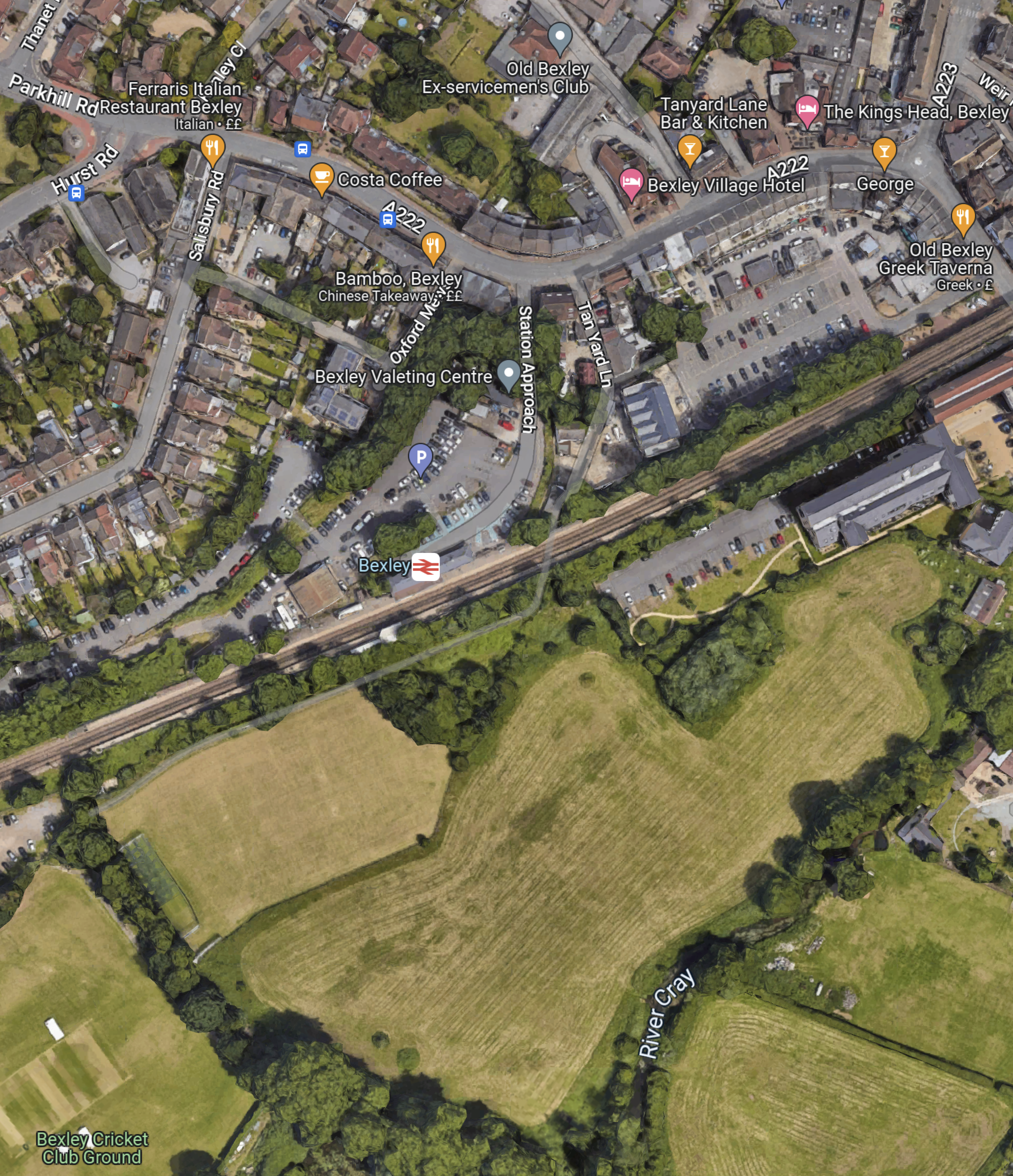
As there appears to be a lot more housing and the car park to the North of the railway, I suspect there’s a lot of crossing of the railway by passengers.
So it does seem that Network Rail have designed scheme for the number of passengers, which is something Transport for London haven’t done with the buses, where I live.
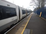
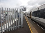
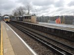
On a visit to the station on the 14th of March, I took these pictures.


This is a Network Rail visualisation of how it will look.
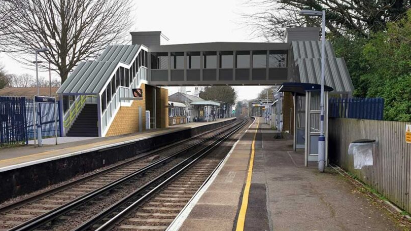
The visualisation is looking towards the East.
World’s First Offshore Vessel Charging System Completes Harbour Trials
The title of this post, is the same as that of this article on offshoreWIND.biz.
This is the sub-heading.
MJR Power and Automation, together with Blackfish Engineering and Tidal Transit, have completed the harbour trials of the company’s platform-mounted automated offshore power and charging system.
Reading the article, this appears to be a very comprehensive system, that allows electric or hybrid wind farm servicing vessels to top up their batteries efficiently before returning to base.
Surely, it is better to do it this way by developing the charging network before bringing the battery and hybrid vessels into service.
Should There Be Five-Car High Speed Two Classic-Compatible Trains?
The High Speed Two Classic-Compatible Trains have the following characteristics.
- Eight cars.
- 200 metres long.
- 550 passengers.
- Two can be coupled together to make a 16-car train, that is 400 metres long.
- Trains can join and split en route.
This graphic shows the preliminary schedule.
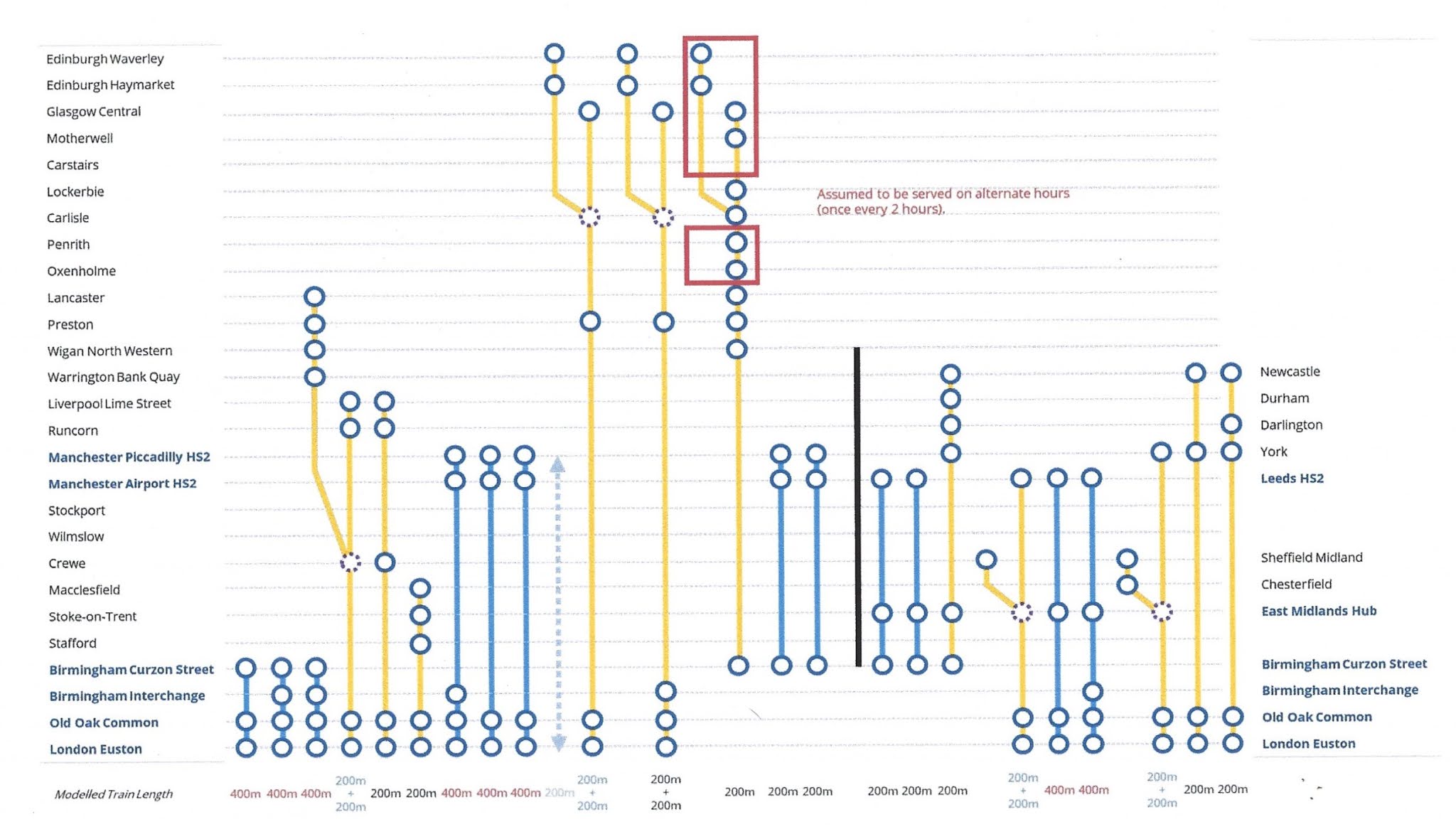
Note that Train 4, starts as a pair of trains, before splitting at Crewe, with one train going to Lancaster and the other to Liverpool Lime Street.
I wonder, if some trains were to be five-cars, would this give the operator more flexibility, by allowing three trains to be coupled together to serve three destinations.
This could be a simple example.
- A three train formation could leave Euston.
- At Crewe one train would detach and go to Liverpool Lime Street, with stops at Runcorn and Liverpool South Parkway.
- At Preston, the two remaining trains would split, with one train going to Lancaster and the other going to Blackpool with appropriate stops.
Three trains might give the operators more flexibility in providing appropriate capacity to various destinations.
Other Applications
I believe these trains would have other applications.
These are a few thoughts.
Battery-Electric High Speed Train
Battery technology is improving and I believe that a train could be designed with the following specification.
- Five cars
- High-Speed Two Classic-Compatible performance.
- A battery pack in each car.
- Up to maximum operating speed of digitally-signalled high speed lines.
- 140 mph on digitally-signalled classic high speed lines, like the East and West Coast Main Lines. the Midland Main Line and the Great Western Railway.
- Range on battery of around 120 miles at 100 mph.
- Ability to work with fully-electric versions.
Note.
- I suspect that like current Hitachi AT-300s and Bombardier Aventras, the onboard computer would know what cars have been coupled together and what the train can do.
- A battery in each car would distribute the extra weight of the batteries equally and not affect the handling too much.
- These trains would allow High Speed Two services to be extended onto non-electrified lines.
I suspect that an eight car battery-electric High-Speed Two Classic-Compatible train would also be possible for working with the standard length trains.
UK Company Introduces Robotic Ecosystem For Offshore Wind Farm Inspections
The title of this post, is the same as that of this article on offshoreWIND.biz.
This is the sub-heading.
Marshall Futureworx, the venture building and advanced technologies arm of Marshall of Cambridge, has unveiled plans to provide offshore wind farm inspection services using a resident robotic ecosystem.
These two paragraphs outline the system.
Lilypad is an ecosystem of multiple autonomous BVLOS (Beyond Visual Line of Sight) UAVs (Unmanned Aerial Vehicles) which utilise artificial intelligence and navigational sensors to provide dynamic and on-demand offshore inspection services, Marshall Futureworx said.
The UAVs are deployed from dedicated offshore charging stations and monitored by a single remote pilot stationed in an onshore command and control centre. Inspection data and reports are then transmitted back to the wind farm operators, which is said to enable faster, more frequent, reliable, and predictive maintenance scheduling and more effective utilisation of assets.
I can think of lots of uses for a system like this.
Maritime UK Launches Offshore Wind Plan
The title of this post, is the same as that of this article on offshoreWIND.biz.
This is the sub-heading.
Maritime UK has unveiled its Offshore Wind Plan which makes a series of recommendations for how the maritime sector, the offshore wind sector, and governments can work together to maximise growth
These are the first three paragraphs and they outline the plan.
The plan outlines how the growth of offshore wind can provide opportunities across the maritime supply chain in sectors like ports, shipbuilding, crewing, and professional services.
Opportunities identified in the Offshore Wind Plan include building vessels in the UK to support developments and further growing UK ports as centres for manufacturing and assembly for offshore developments
Key recommendations and proposals within the plan include: creating quality career pathways for young people; rewarding higher UK supply chain content in offshore wind projects; reforming the planning system to enable green projects to be delivered quicker; and encouraging lenders and investors to finance infrastructure and vessels
Note.
- Maritime UK have a web site.
- The report seems to be comprehensive.
- The report predicts hundreds of ships to build and service wind farms will be needed.
Overall, Maritime UK feel that the maritime sector has a lot to gain from co-operation with the offshore wind sector.
Improved Service Operation Vessels (SOVs)
I don’t see why the large number of Service Operation Vessels (SOVs) needed to serve all the wind farms around our shores, can’t be designed and substantially built in the UK.
In the 1970s, one of Metier Management Systems’ customers for Artemis were the shipbuilders; Austin & Pickersgill, who at the time were building a cargo ship called the SD14, which had been designed to replace the American Liberty ships.
In total 211 SD14s were built in the UK, Greece, Brazil and Argentina.
SD14 stands for Shelter Deck – 14,000 tonnes.
We surely have the technology from companies like BAe Systems, Rolls-Royce and others to design an advanced Service Operation Vessel.
X1 Wind’s Floating Prototype Delivers First Power Offshore Canary Islands
The title of this post, is the same as that of this article on offshoreWIND.biz.
This is the sub-heading.
X1 Wind has announced that its floating offshore wind turbine prototype delivered first power to PLOCAN’s smart grid in the Canary Islands, Spain.
The article is based on this news item from X1 Wind, which is entitled X1 Wind’s X30 Floating Wind Prototype Delivers First kWh, which starts with these two paragraphs.
X1 Wind has announced today (MARCH 07) that its X30 floating wind prototype, installed in the Canary Islands, successfully produced its first kWh.
The milestone marks the world’s only floating wind platform currently installed with a TLP mooring system, which dramatically reduces the environmental footprint and improves compatibility with other sea uses. It further heralds Spain’s first floating wind prototype to export electricity via a subsea cable.
Note.
- TLP is short for tension leg platform, which is described in this Wikipedia entry.
- The TLP Wikipedia entry contains a section, which describes their use with wind turbines.
- TLPs have been in use for over forty years, with the first use in the Hutton field in the North Sea.
- TLPs work well for water depths of between 300 and 1,500 metres.
I also suspect there’s a lot of experience from the oil and gas industry around the world about how to deploy TLPs.
The X1 Wind news item also has this paragraph.
The novel X30 platform is equipped with a specially adapted V29 Vestas turbine and ABB power converter. Another key design feature, developed through the EU-backed PivotBuoy Project, combines advantages of SPM and TLP mooring systems. The proprietary SPM design enables the floater to ‘weathervane’ passively and maximise energy yields, with an electrical swivel ensuring electricity transfer without cable twisting. The TLP mooring system also dramatically reduces the seabed footprint, compared to traditional designs proposing catenary mooring lines, minimizing environmental impact while maximizing compatibility with other sea uses, in addition to its suitability to move into deeper waters.
SPM is short for single point mooring, which is described in this Wikipedia entry, where this is the first sentence.
A Single buoy mooring (SrM) (also known as single-point mooring or SPM) is a loading buoy anchored offshore, that serves as a mooring point and interconnect for tankers loading or offloading gas or liquid products. SPMs are the link between geostatic subsea manifold connections and weathervaning tankers. They are capable of handling any tonnage ship, even very large crude carriers (VLCC) where no alternative facility is available.
Note.
- The use of the weathervane in both paragraphs.
- If an SPM can handle a VLCC, it surely can handle a well-designed floating structure with a wind turbine mounted on top.
- I suspect that an SPM used for a wind turbine will be much simpler than one used to load or unload a gas or oil tanker.
As with TLPs, I also suspect there’s a lot of experience from the oil and gas industry, from around the world about how to deploy SPMs.
It looks to me, that X1 Wind have used the proven attributes of SPMs and TLPs to create a simple mooring for a wind turbine, that is designed to align itself with the wind.
X1 Wind Are Open With Their Technology
Today’s news item from X1 Wind also links to two other useful documents.
- X1 Wind Adaptation Of A Vestas V29 Turbine To Downwind Configuration
- X1 Wind Successfully Installs Floating Wind Platform In Spain
They are certainly open with their information.
The news item, also includes this video.
Thoughts
These are some thoughts.
Capacity Factor
The capacity factor of this wind turbine could be an interesting figure.
As the turbine constantly will turn to be downwind, this should maximise the amount of electricity produced over a period of time.
Tetrahedrons
The design is effectively a tetrahedron.
Alexander Graham Bell knew a lot about the properties of tetrahedrons and invented the tetrahedral kite.
This document details Bell’s involvement with tetrahedrons and says this.
Bell found the tetrahedron to have a very good strength to weight ratio.
Put more simply this means that an object is structurally very strong but at the same time very lightweight.
So X1 Wind’s design is probably extremely strong for its weight.
Large Turbines
X1 Wind’s prototype uses a wind turbine of only 225 KW.
Manufacturers are building 15 or 16 MW turbines now and talking of 20 MW in the next few years.
Given the strength of the tetrahedron, I wonder, if it will be possible to build a PivotBuoy, that is capable of hosting a 20 MW wind turbine?
Conclusion
Although it appears radical, it uses proven technology to generate power in an innovative way.
In some ways the thinking behind the design of this floating technology, is a bit like that of Issigonis in his design for the first Mini, where he took proven technology and arranged it differently to perform better.
Would It Be Possible For The Bakerloo And Watford DC Lines To Use The Same Trains? – 6th March 2023 Update
These two lines are very different.
- The Bakerloo Line is a classic London Underground Line with 25 stations and services run by 1972 Stock trains.
- The Watford DC Line is part of the London Overground with 19 stations and services run by Class 710 trains.
Ten stations are shared between the lines, of which only one; Queen’s Park offers level boarding.
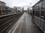
The Shared Stations
The nine shared stations often have considerable steps up and down, as at Willesden Junction station, which is shown in Train-Platform Interface On Platform 1 At Willesden Junction.
I am rather pleased and pleasantly surprised, that there are not more accidents at the shared stations, but using the line must be a nightmare for wheelchair users, buggy pushes and large case draggers.
If Transport for London proposed building a line like this, they would have to launch it at the Hammersmith Apollo, where comedians perform.
The One Train Type Solution
To my mind, there is only one solution. The two services must use the same type of trains.
These are a few thoughts on the trains.
Trains Would Be Underground-Sized
As the trains will have to work through the existing tunnels to Elephant & Castle station, the trains would have to be compatible with the tunnels and therefore sized for the Underground.
I suspect they would be a version of the New Tube for London, that are currently being built by Siemens for the Piccadilly Line.
New Tube For London And Class 710 Train Compared
This Siemens infographic summarises the New Tube For London.
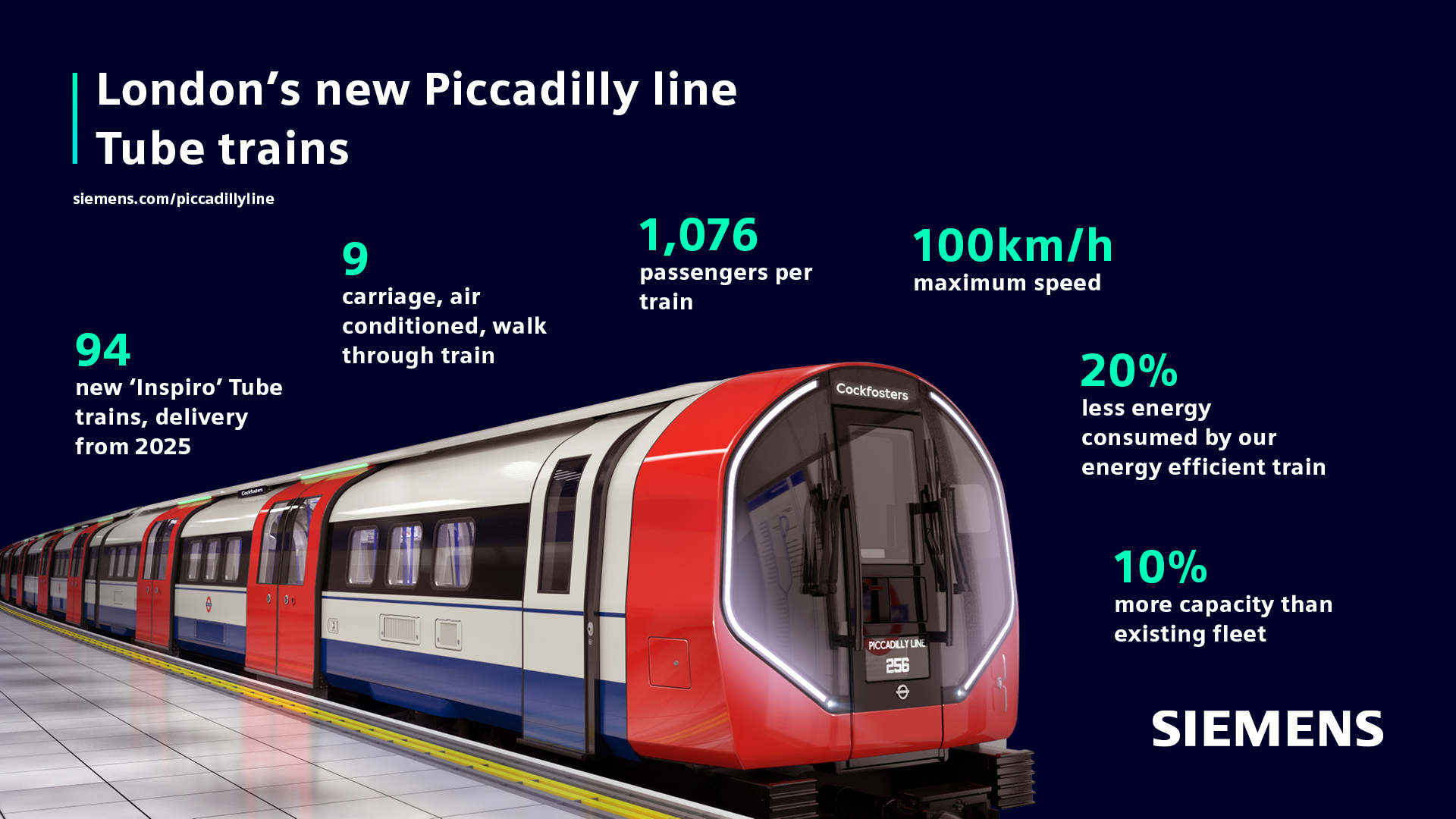
These figures are from Wikipedia.
- Cars – NTFL – 9 – 710 – 4
- Car Length – NTFL – 12.6 metres – 710 – 20 metres
- Train Length – NTFL – 113.4 metres – 710 – 80 metres
- Seated Passengers – NTFL – 268 – 710 – 189
- Total Passengers – NTFL – 1076 – 710 – 678
- Passenger Density – NTFL – 9.5 per metre – 710 – 8.2 per metre
- Speed – NTFL – 62 mph – 710 – 75 mph
Note.
- The figures for the Class 710 train are for a four-car train.
- The passenger density and speed are closer than I thought they’d be.
- I’m sure Siemens can design a longer and/or faster train if required for the Euston service.
I feel that the New Tube for London design could be adjusted , so that it could work the Watford DC service.
Platform Modifications
I suspect that the New Tube for London will be lower than the Class 710 train and all platforms would need to be lowered to fit the new trains.
I would also suspect that it would be easier to lower platforms, than modify them, so that they had dual-height sections to satisfy two classes of train.
It should be noted that the New Tube for London has shorter cars than the sixteen metre 1972 Stock trains currently used on the line, so there will be smaller gaps at stations with curved platforms like Waterloo.
I believe that with one class of train, all of the stations on the Bakerloo and Watford DC Lines could be made step-free between train and platform.
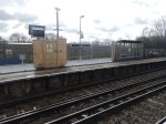
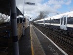
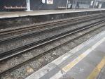
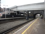
Platform Height On Platform 9 At Euston
I took these pictures on Platform 9 at Euston station.
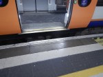
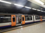
Note that it is rather a high step into the train and there is a large gap.
But if say, a modern London Underground train from say the Victoria Line pulled into the platform would it be a better fit?
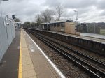
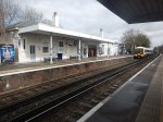
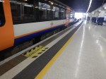
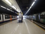
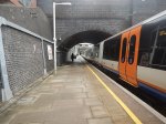
Platform Height At Kilburn High Road Station
These pictures show Kilburn High Road station.


I should have taken more pictures, but the step between the platform and train is similar to Platform 9 at Euston.
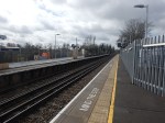
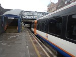
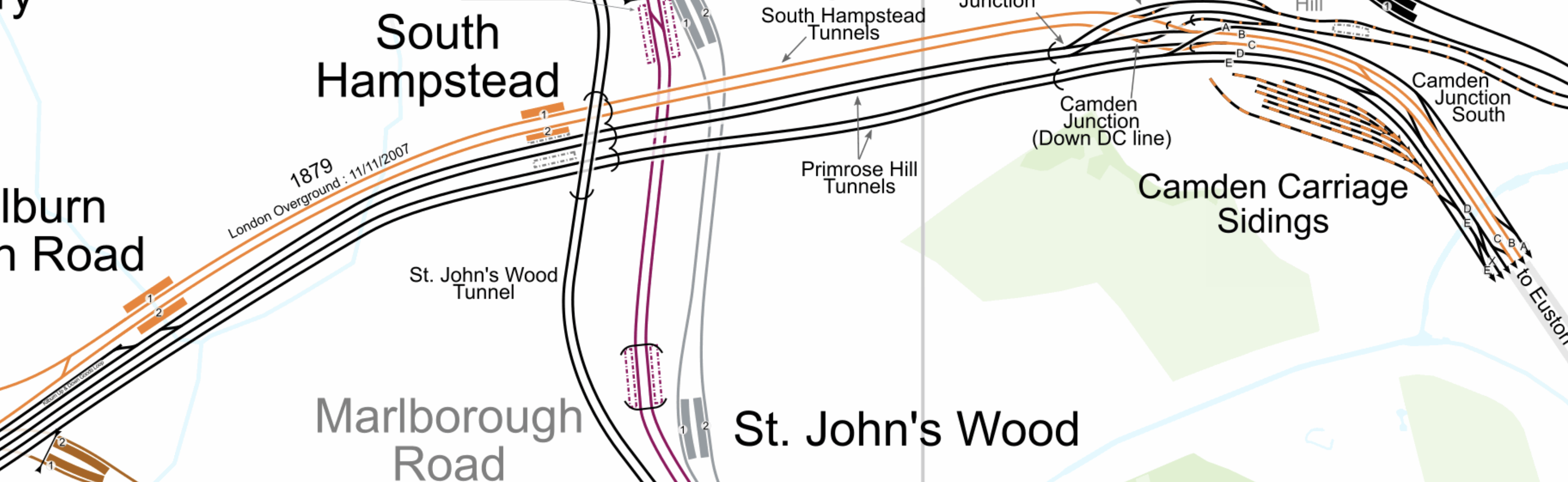
Platform Height At South Hampstead Station
These pictures show South Hampstead station.


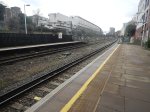


I should have taken more pictures, but again the step between the platform and train is similar to Platform 9 at Euston.
Were The Platforms At Euston, South Hampstead And Kilburn High Road Built For Another Class Of Train?
This Wikipedia entry is for the London Underground Watford Joint Stock train, where this is said.
The Watford Joint Tube Stock was built for the service to Watford along both the Bakerloo tube and the London North Western Railway. As a result, the cars were owned by both the Underground and the London North Western Railway. To be able to operate on both lines, the car floors were 4+1⁄2 inches (110 mm) higher than other tube cars. This was a compromise height between the platform heights on the two lines.
The cars were ordered in 1914, but construction was delayed by The First World War. As a result, the first cars were not delivered until early 1920.
Note.
- The Wikipedia entry has links to some images of which this is one.
- They must have been rather cramped trains if they were built for deep tunnels and had a floor that was 110 mm higher, than other tube trains.
It certainly appears to be possible to design a train, that would fit both lines.
But would it fit modern regulations and give full step-free access?
Queen’s Park And Euston
This map from cartometro.com, shows the route between Queen’s Park and Euston stations.
Note.
- The Watford DC Line is shown in orange.
- Queen’s Park station is to the West of Kilburn High Road station.
- It appears that Watford DC Line trains always use Platform 9 at Euston station.
The route seems to be a self-contained third-rail electrified line into Euston station.
On the subject of electrification between Queen’s Park and Euston stations, there would appear to be a choice between the third-rail system and London Underground’s four-rail system.
But it is rumoured that the New Tube for London will have a battery capability.
As Euston and Queen’s Park stations are only 3.7 miles apart, perhaps the choice would be to use battery power into Euston station, which would remove electrified rails from Euston?
How Many Trains Could Run Into Euston?
Currently, four trains per hour (tph) run into Euston.
It is generally accepted that six tph can use a single platform. But would this be enough?
I suppose there is the possibility of tunnelling under Euston station to a pair of terminal platforms.
In that case the current platform could be used by other services.
Southern’s Milton Keynes And Clapham Junction Service
This service wouldn’t be affected as it uses the fast lines between Willesden and Watford Junction.
Advantages Of One Train Type On The Bakerloo And Watford DC Lines
I can think of these advantages.
- Step-free access between train and platform, should be achieved.
- A unified fleet.
- A higher frequency between Euston and Willesden Junction stations.
- Higher frequency where needed.
- If trains had a battery capability, Euston could be free of third-rail electrification.
As only one type of train will be using the Watford DC line between Euston and Watford Junction, this could result in operational efficiencies.
Linking Of The Bakerloo And Abbey Lines
This could be the biggest advantage of all.
This map from cartometro shows the lines at Watford Junction station.
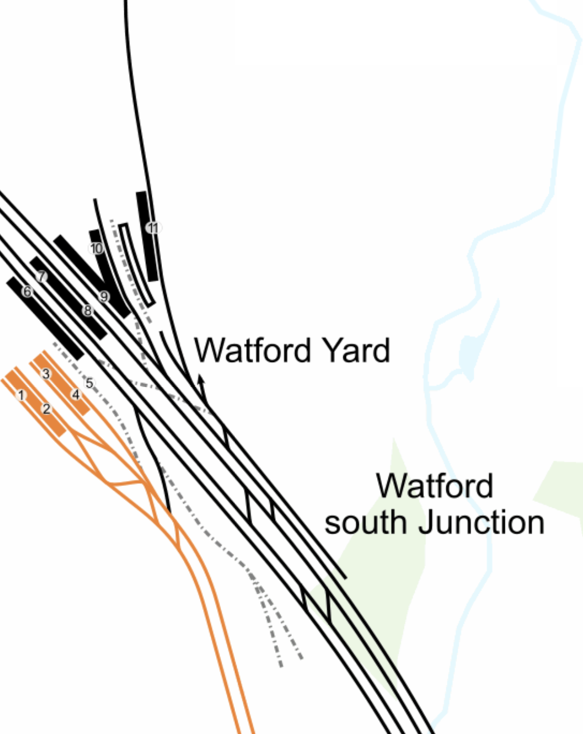
Note.
- The orange lines are the current Watford DC Line services of the London Overground, terminating in platforms 1 to 4 of Watford Junction station.
- These lines would be taken over by the unified Bakerloo/Watford DC Line services, running nine-car New Tubes For London.
- The next station to the South is Watford High Street.
- The West Coast Main Line goes through the station and uses platforms 5 to 10.
- At the North of the station is Platform 11 on the Abbey Line which leads roughly North East to St. Albans.
Look at how the Abbey Line is more or less in line with the twin-tracks of the Watford DC Line.
Recently, during the Bank Station Upgrade, a 488 metre long single track tunnel was built to divert the Southbound Northern Line.
This tunnel was not dug with a tunnel boring machine, but traditionally by hand, using men, picks, shovels and I suspect a few small machines.
I believe, that a similar technique could be used to dig a tunnel, to connect the Abbey Line and the Watford DC Line.
- It would only be single-track
- It would probably be less than 500 metres long.
- It would connect to the Abbey Line to the South of Platform 11.
- It would be deep-level tube-sized.
- It might be dug by hyperTunnel.
- Geography wouldn’t allow the tunnel to terminate in the Watford DC Line platforms at Watford Junction station.
But where would the terminal be on the Southern side of the West Coast Main Line?
This map from OpenRailwayMap, shows the two routes between Watford Junction and Bushey stations.

Note.
- Watford Junction station is at the top of the map.
- The orange line is the West Coast Main Line.
- The yellow line looping to the West of the West Coast Main Line is the double-track Watford DC Line.
- Bushey station is at the bottom of the map, where the two rail lines meet.
- Watford High Street station is in the middle of the map on the Watford DC Line.
The new service could certainly take the Watford DC Line as far as Watford High Street station.
- The station is close to the centre of Watford, the hospital and Vicarage Road stadium.
- But there is no space for a terminal platform.
This second OpenRailwayMap shows the disused railways to the West of Watford High Street station.
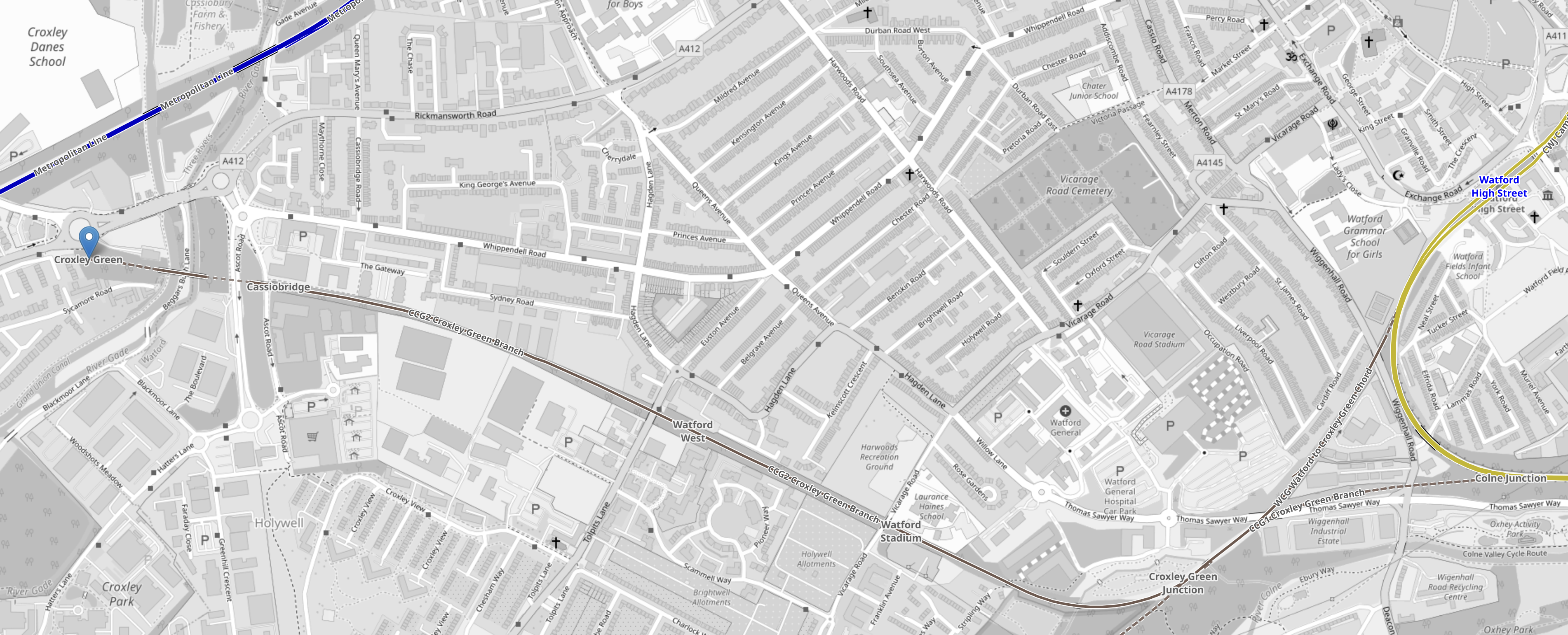
Note.
- The yellow loop at the East of the map is the Watford DC Line.
- Watford High Street station is on this loop.
- There is a triangular junction, that connects the former Croxley Green branch to the Watford DC Line.
- The terminus at Croxley Green station is marked by a blue arrow.
- There used to be intermediate stations at Cassiobridge, Watford West and Watford Stadium.
- This route was used for the failed attempt to build the Croxley Rail Link.
But could a Western extension of the Abbey Line be built?
- It would terminate at either Croxley Green or Cassiobridge.
- There would be intermediate stations at Watford West, Watford Stadium and Watford High Street.
- There would be two tph.
- Trains would be nine-car New Tubes For London.
- The current Abbey Line is 6.4 miles and would be run using battery power, with possible charging at St. Albans Abbey station.
- The tunnel under the West Coast Main Line would be run on battery power.
- The Western extension from Watford High Street station would be run using battery power, with possible charging at the Western end.
I believe, an extended Abbey Line could be a viable alternative to the ill-fated Croxley Rail Link.
- I have used battery power, as I doubt Health and Safety would allow any new third-rail electrification.
- I have used nine-car New Tubes For London for the extended Abbey Line, as their small cross-section would allow a smaller tunnel and they would be certified for running in tunnels.
- Some platforms on the Abbey Line would need to be lengthened, but these would be the only modifications, other than the possible installation of the charging system.
- The extended Abbey Line would serve Watford Hospital and Vicarage Road.
The capacity of the extended Abbey Line would be substantially more than the current line.
Conclusion
A common fleet used by the Bakerloo and Watford DC Line would appear to give advantages and it has been done successfully before.
But what the Bakerloo Line, the Watford DC Line, the Abbey Line and the Bakerloo Line Extension need is a good dose of holistic design.
Universal Hydrogen Successfully Completes First Flight Of Hydrogen Regional Airliner
The title of this post, is the same as that of this article on Hydrogen Central.
These two paragraphs outline the story.
Universal Hydrogen successfully completes first flight of hydrogen regional airliner.
Universal Hydrogen Co., this morning flew a 40-passenger regional airliner using hydrogen fuel cell propulsion. The airplane, nicknamed Lightning McClean, took off at 8:41am PST from Grant County International Airport (KMWH) and flew for 15 minutes, reaching an altitude of 3,500 MSL. The flight, conducted under an FAA Special Airworthiness Certificate, was the first in a two-year flight test campaign expected to culminate in 2025 with entry into passenger service of ATR 72 regional aircraft converted to run on hydrogen.
Other details from the article include.
- Connect Airlines are the North American launch customer, who have ordered 75 aircraft conversions.
- Amelia are the European launch customer.
- Universal Hydrogen has an order book, totaling 247 aircraft conversions from 16 customers worldwide.
- For the test flight, only one engine was replaced by a hydrogen fuel cell powered electric motor.
- Deliveries will start in 2025.
The article finishes with two paragraphs about Universal Hydrogen.
Universal Hydrogen is building a hydrogen logistics network to fuel the future of aviation, today. Hydrogen is the ideal fuel for flight and will power aviation’s new golden age, where planes are powered by renewables and emit nothing but water. The company’s modular hydrogen capsules move over the existing freight network from production directly to the airplane anywhere in the world.
Universal Hydrogen is also working to certify a powertrain conversion kit to retrofit existing regional aircraft to fly on hydrogen. The company has gathered the world’s leading aviation and hydrogen talent to give the industry the option of clean flight, forever.
The company also has an unusual web site.
I like the company and its design, operating and marketing philosophies.
Belgians To Start Building World’s First Artificial Energy Island Next Year (VIDEO)
The title of this post, is the same as that, of this article on offshoreWIND.biz.
This is the sub-heading.
Belgian offshore construction companies Jan De Nul and DEME, through their consortium TM EDISON, have won the tender for the construction of the Princess Elisabeth Island in their home country and the first artificial energy island in the world.
And this first paragraph outlines the project.
The artificial island, which will be built some 45 kilometres off the Belgian coast and will occupy an area of approximately five hectares above the waterline, will serve as the link between the offshore wind farms in the country’s second, 3.5 GW Princess Elisabeth offshore wind zone and its onshore high-voltage grid.
Initial plans don’t seem to be putting any wind turbines or solar panels on the island.
The most impressive part of the article is the video, which shows how the island will be constructed.
To some people of my age, the construction of the island will seem familiar, as the island will be built in a similar way to the Mulberry harbours of World War II.
A few years ago, I went inside some of the giant Pheonix caissons in The Netherlands, where they were initially used to plug the dykes after the North Sea Flood of 1953. They are now a museum of the floods called the Watersnoodmuseum.
Engineering is repeating itself.
