Repurposing The Tummel Hydro-Electric Scheme
The Tummel hydro-electric scheme was built in the 1930s and 1950s, by the North of Scotland Hydroelectric Board.
- The scheme is now owned by SSE Renewables and has a page on their web site.
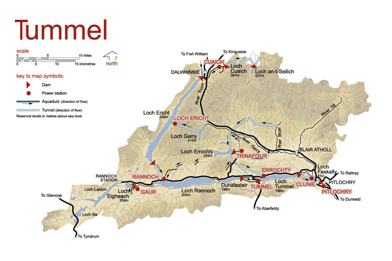
- There are nine individual power stations; Gaur, Cuaich, Loch Ericht, Rannoch, Tummel, Errochty, Trinafour, Clunie and Pitlochry.
- There are four dams; Gaur, Errochty, Clunie and Pitlochry.
This map from the SSE Renewables web site shows the layout of the dams and power stations.
This description of the scheme is from Wikipedia.
The Tummel hydro-electric power scheme is an interconnected network of dams, power stations, aqueducts and electric power transmission in the Grampian Mountains of Scotland. Roughly bounded by Dalwhinnie in the north, Rannoch Moor in the west and Pitlochry in the east it comprises a water catchment area of around 1,800 square kilometres (690 sq mi)[1] and primary water storage at Loch Ericht, Loch Errochty, Loch Rannoch and Loch Tummel, in Perth and Kinross. Water, depending on where it originates and the path it takes, may pass through as many as five of the schemes nine power stations as it progresses from north-west to south-east. The scheme was constructed in the 1940s and 50s incorporating some earlier sites.
Note.
- There are no underground power stations.
- The scheme is what is known as a run-of-the-river hydroelectric scheme.
The sizes of the power stations in the scheme are as follows.
- Gaur – 75 MW
- Cuaich – 2.5 MW
- Loch Ericht- 2.2 MW
- Rannoch – 44 MW
- Tummel – 34 MW
- Errochty – 75 MW
- Trinafour – 0.5 MW
- Clunie – 61 MW
- Pitlochry – 15 MW
This gives a total power of 309.2 MW.
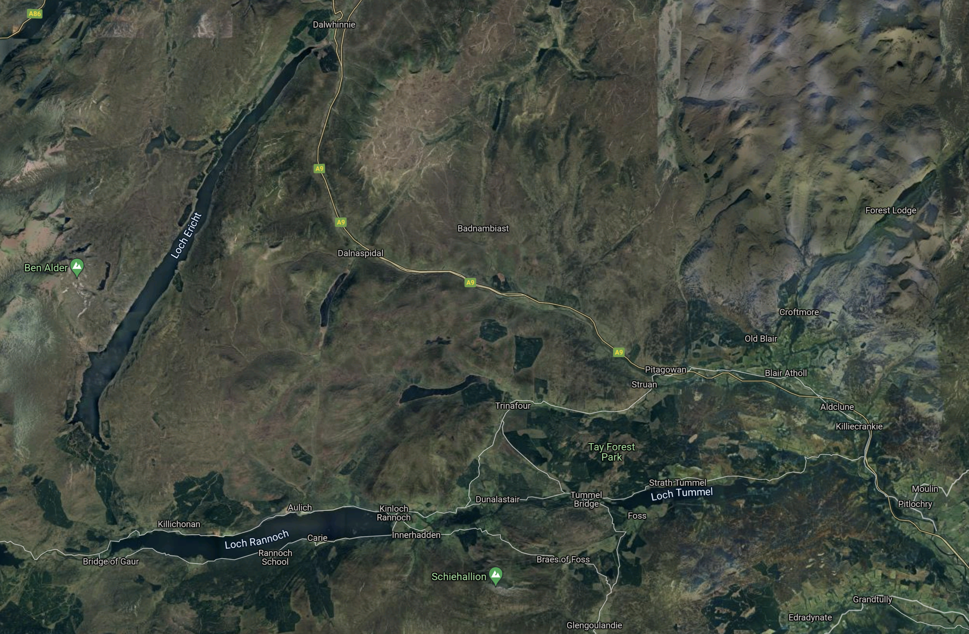
This Google Map shows the same area as the SSE Renewables Map.
Note.
- Dalwhinnie is at the North of the map.
- Gaur is in the South-West corner of the map.
- Pitlochry is in the South-East corner of the map.
There are no underground power stations.
Strathclyde University And Pumped Storage Power For Scotland
This page on the Strathclyde University gives a list of the pumped storage potential for Scottish hydrogen-electric dams and power stations.
These figures are given for the dams and lochs in the Tummel scheme.
- Errochty – 16 GWh
- Clunie – 40 GWh
- Rannoch – 41 GWh
- Tummel – 38 GWh
It would appear that based on research from Strathclyde University, that the Tummel scheme could support over 120 GWh of pumped storage.
Water Flows In The Tummel Scheme
Looking at the SSE Renewables map of the Tummel scheme and reading this section in the Wikipedia entry for the Tummel scheme, which is entitled Water Route, water flows appear to be as follows.
- Loch an t-Seilich to Loch Cuaich
- Loch Cuaich to Loch Ericht via Cuaich power station and the Cuaich aqueduct
- Loch Garry to Loch Ericht via Ericht power station.
- Loch Ericht to Loch Rannoch
- Loch Eigheach to Loch Rannoch via Gaur power station
- Loch Rannoch to Dunalastair Water via Kinloch Rannoch weir
- Dunalistair Water to Loch Tummel via Tummel power station
- River Bruar and River Garry to Loch Errochty
- Loch Errochty to Loch Tummel via Errochty power station
- Loch Errochty to Trinafour power station
- Loch Tummel to Loch Faskally via Clunie power station
- Loch Faskally to Pitlochy power station
Note.
Water from Loch an t-Seilich can take various routes to Clunie and Pitlochry power stations.
Water from Loch Eigheach goes through Loch Rannoch, Dunalistair Water and Loch Tummel to Clunie and Pitlochry power stations.
It seems a complicated scheme but it does have a capacity of 307 MW, which compares with 389 MW of Bankside power station.
Refurbishing And Repurposing The Tummel Scheme
Perhaps as the power stations are now over fifty years old, one simple way to increase the generating capacity of the Affric/Beauly scheme might be to selectively replace the turbines, with modern turbines, that can generate electricity more efficiently.
I suspect that SSE Renewables have an ongoing program of improvements and replacements for all of their hydro-electric stations in Scotland. Some turbines at Sloy power station have already been replaced with larger ones.
In The Affric/Beauly Hydro-Electric Scheme, I wrote about the control system needs of that scheme, which I felt could be fairly challenging.
I suspect the control of the Tummel scheme is equally challenging.
Adding Pumped Storage To The Tummel Scheme
I’ll look at each possibility in turn.
Loch Errochty
Strathclyde University estimated that 16 GWh of pumped storage could be added to Loch Errochty.
This Google Map shows the Eastern end of Loch Errochty.
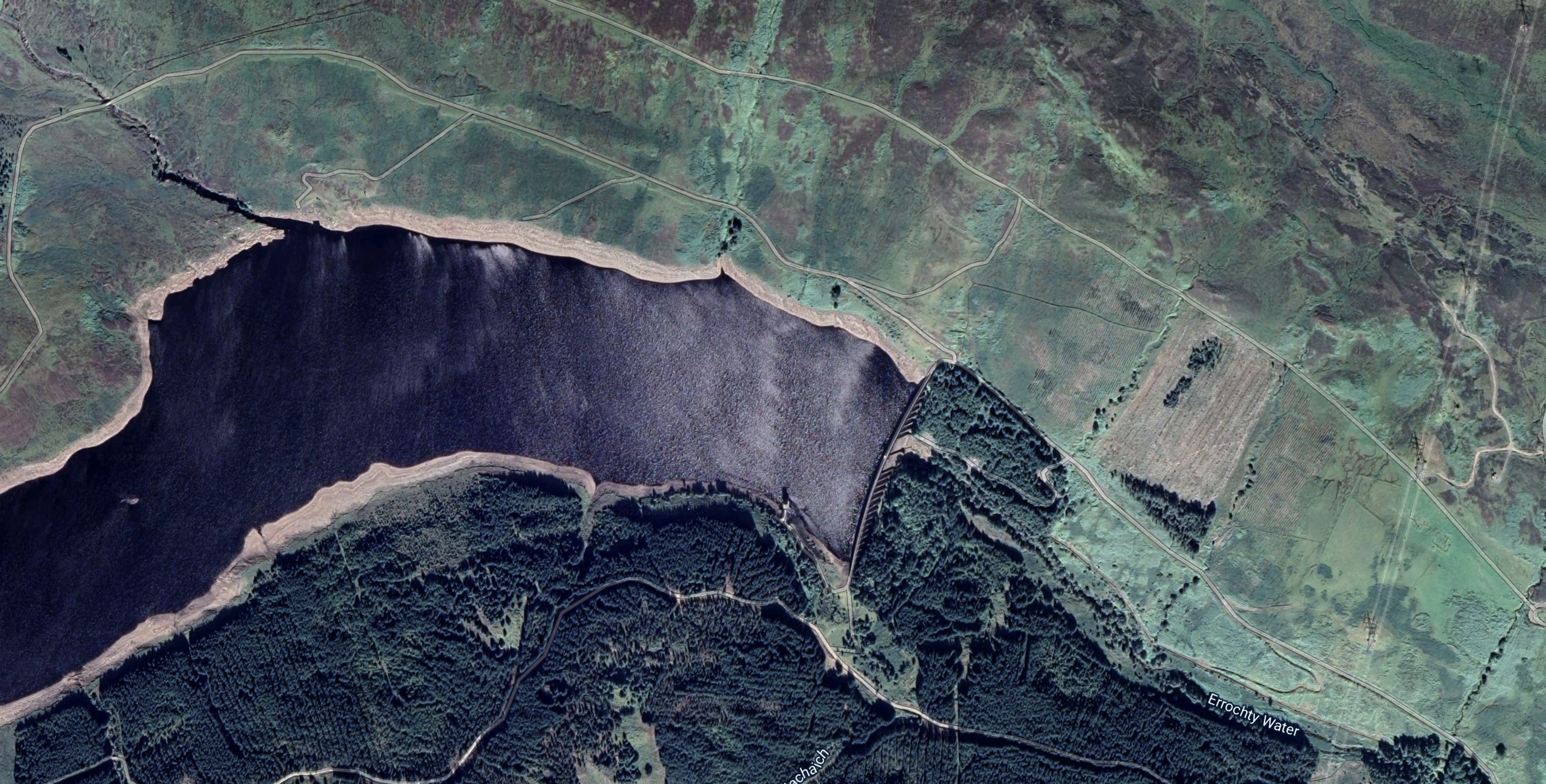
Note the dam at the Eastern end of the loch.
- The dam is 354 metres long by 49 metres high.
- The dam was built in 1957 and the lake is man-made.
- The loch stands at 330 metres above sea level.
- Water flows from the loch to the Errochty power station at the Western end of Loch Tummel, through a ten kilometre long tunnel.
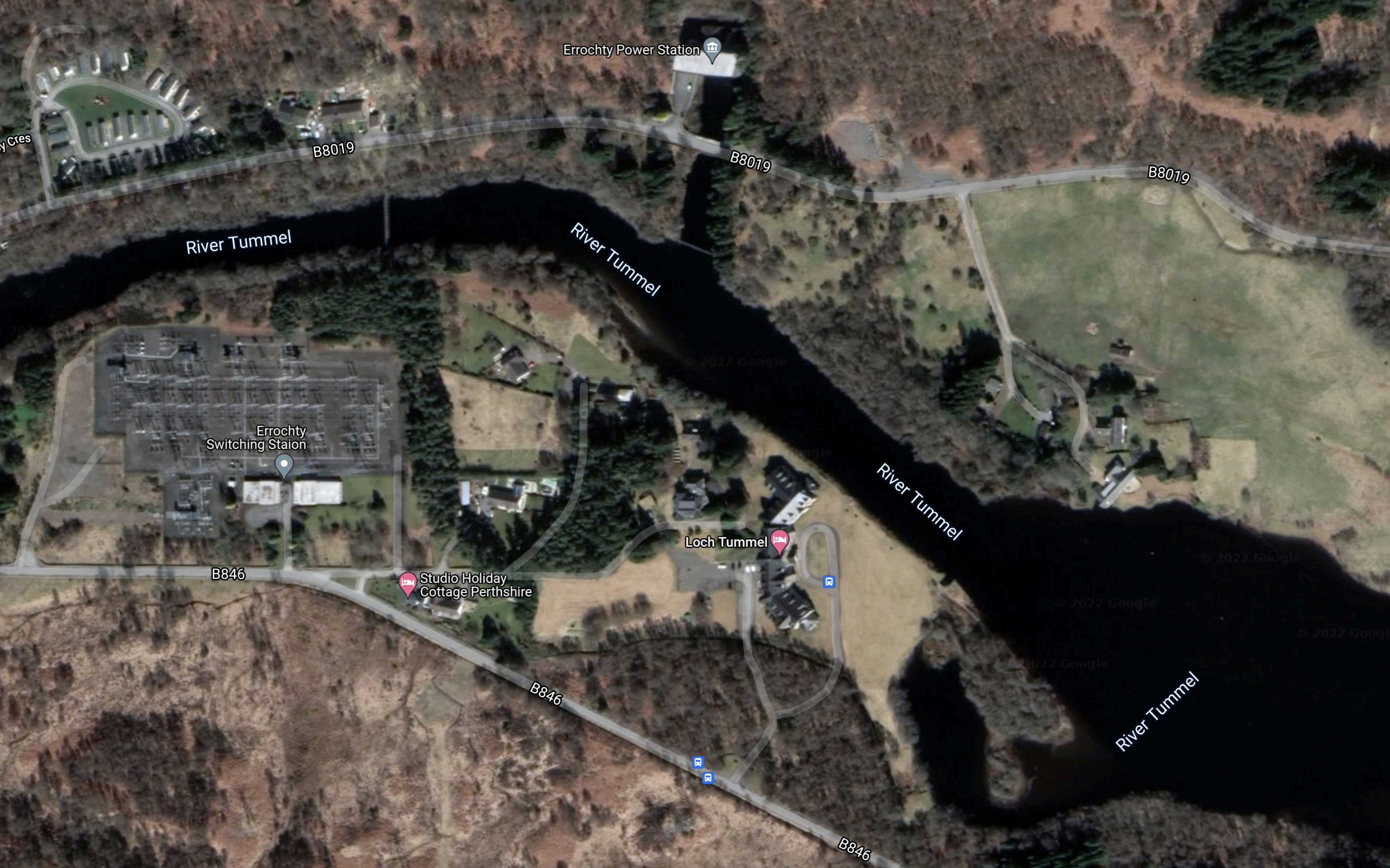
This Google Map shows Errochty power station and Loch Tummel.
Note.
- Errochty power station is at the top of the map in the middle on the channel connecting it to the River Tummel.
- Errochty power station has two turbines and a maximum output of 75 MW.
- There is what appears to be a large switching station at the Western side of the map.
I obviously don’t know for sure, but I suspect this could be an easier scheme to convert, if the current turbines could be replaced with pump/turbines.
There is a section with the title; Water Supply To The Loch in the Wikipedia entry for Loch Errochty, where this is said.
Loch Errochty’s main feeder streams are the Allt Sléibh and the Allt Ruighe nan Saorach which both rise in the high ground to the west of the head of the loch. Other small streams flow directly off the 892-metre-high (2,927 ft) mountain of Beinn a’ Chuallaich which stands just to the south. Supplementary water is diverted into the loch from the east by the Errochty catchwater, a system of tunnels and surface pipelines at a height of approximately 380 metres which redirects water from five small tributary streams of the River Garry, and the Garry itself. The catchwater then goes through a tunnel in the hill which separates the Garry and Errochty valleys to join the loch. This method of re-directing water allows it to be used more often to generate electricity. Some of the water within the Tummel scheme passes through five of the power stations and thus generates electricity five times.
That strikes me as being very sophisticated for the 1950s and if the engineering and tunnels are up to a high standard, it might be that conversion of this power station to a 75 MW power station with 16 GWh pumped storage is a distinct possibility.
It might even be possible to increase the generating capacity of the power station.
Clunie
Strathclyde University estimated that 40 GWh of pumped storage could be added above Clunie power station.
This Google Map shows the River Tummel between Clunie and Pitlochry power stations.
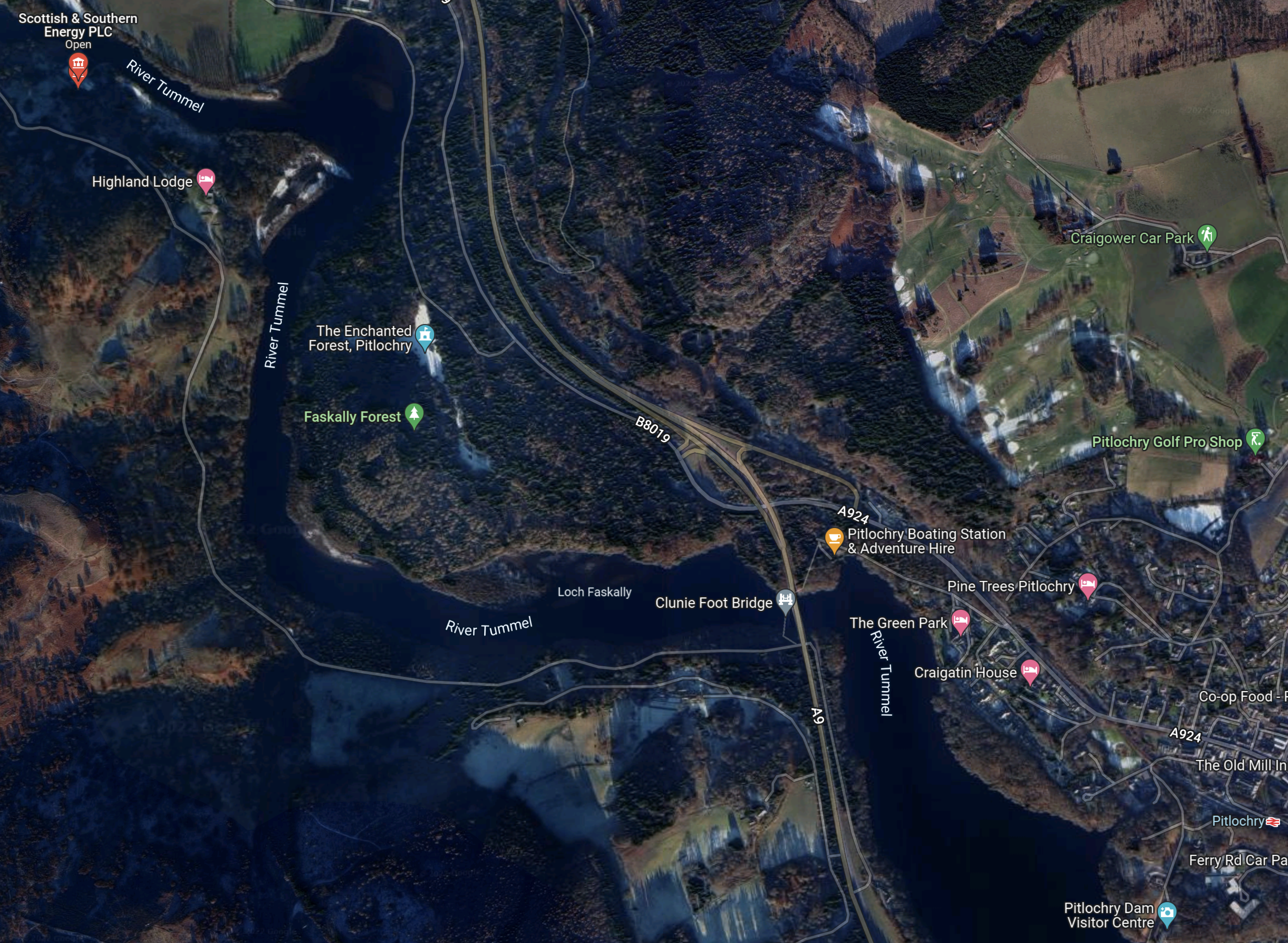
Note.
- Clunie dam and power station is marked by a red arrow labelled Scottish and Southern Energy in the North-West corner of the map.
- Pitlochry Dam and power station are in the South-East corner of the map.
- River Tummel and Loch Faskally link the two dams.
There is a large volume of water between the two dams.
In a pump-back hydro-electric water is pumped back from the lake below the dam into the reservoir above the dam. Such a system was added to the Grand Coulee Dam in the United States to increase its generating and storage capacity.
This Google Map shows how the water to the West of Clunie dam and power station stretches to the other end of Loch Tummel.
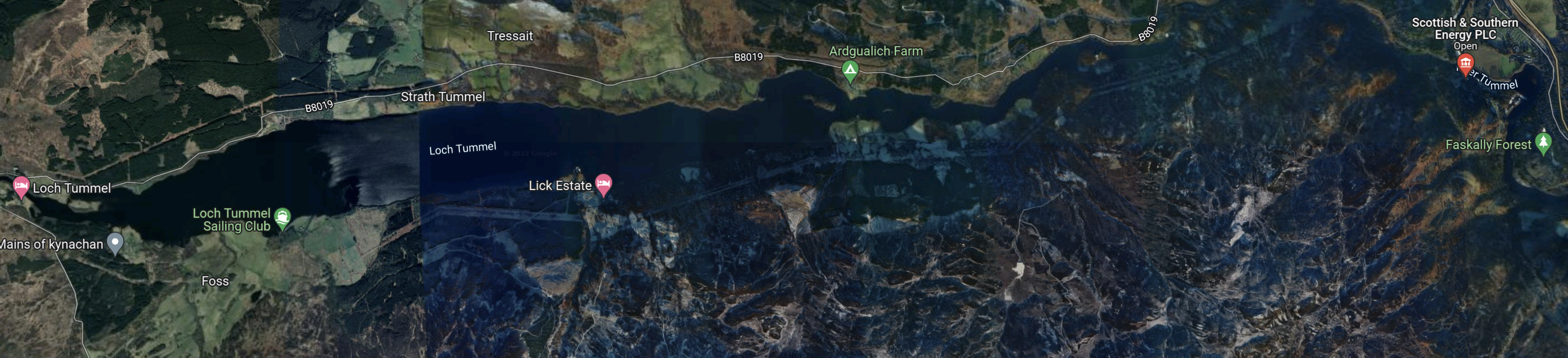
As there would be large volumes on both sides of the dam, I am fairly sure, that a pump-back system could be employed at Clunie power station.
Whether 40 GWh of storage could be added, would be one for the designers of the rebuilt dam and power station?
Tummel
Strathclyde University estimated that 38 GWh of pumped storage could be added above Tummel power station.
This Google Map shows the Eastern end of Loch Rannoch, Dunalastair Water, the River Tummel and Tummel power station.
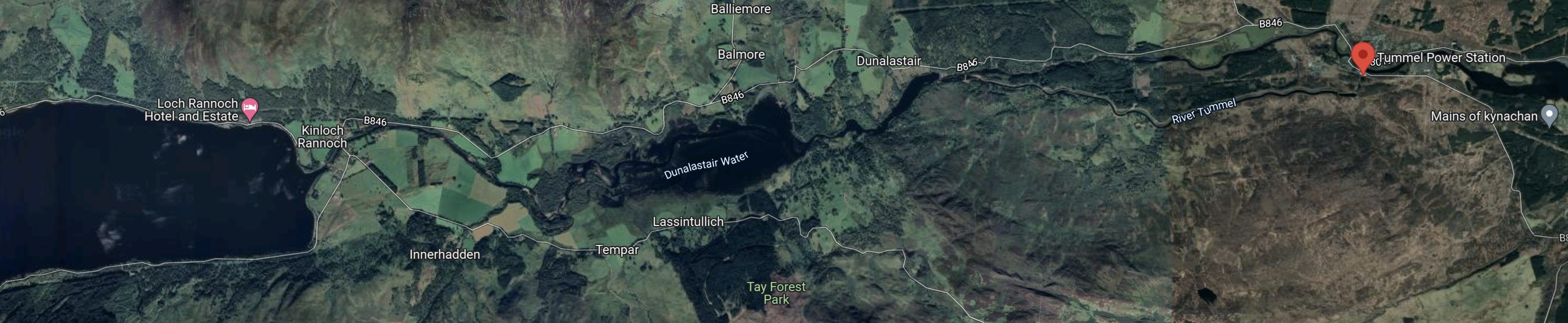
Note.
- Loch Rannoch is at the Western end of the map.
- Dunalastair Water is the smaller lake in the middle.
- Tummel power station is indicated by the red arrow at the East of the map.
This Google Map shows Tummel power station.
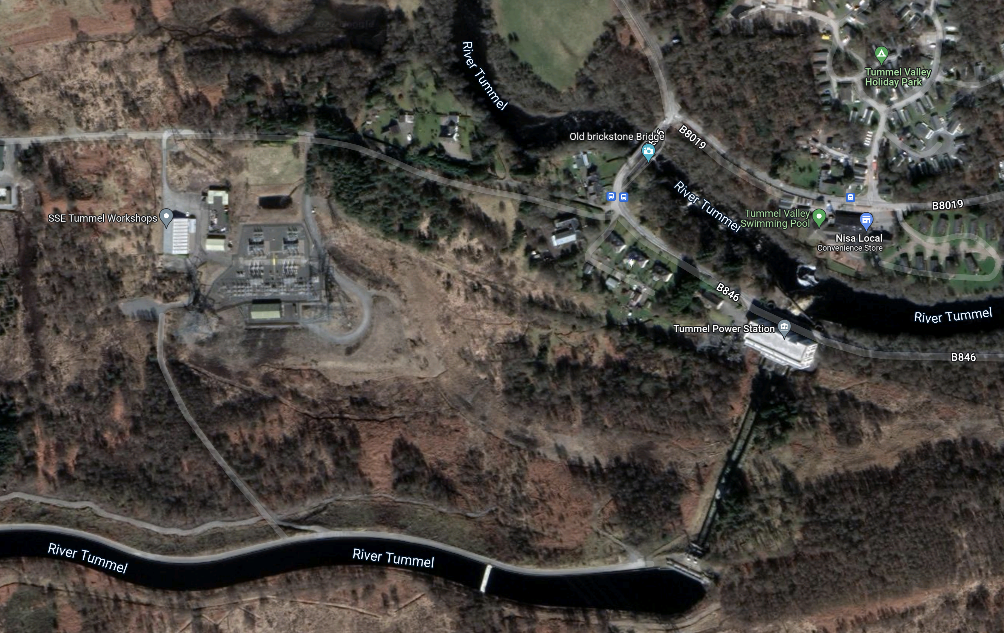
Note.
There appears to be two branches of the River Tummel.
- At the bottom of the map, it appears to be in an aqueduct and above the power station.
- Running across the top-right corner of the map, the second branch appears to be a low-level branch of the river.
- The height difference will mean that power station works well and generates its full 34 MW.
As with Clunie power station, I am sure there is scope for Tummel power station to pump water from Loch Tummel to Dunalastair water, when there is a surplus of wind-generated electricity.
But could space be found above Tummel power station to store enough water to create a massive 38 GWh pumped-storage power station?
Rannoch
This description of Lord Rannoch is from Wikipedia.
It is over 15 kilometres (9.3 mi) long in a west–east direction with an average width of about 1.2 kilometres (0.75 mi), and is deepest at its eastern end, reaching a depth of 130 metres (440 ft).
The loch could hold almost a half a billion tonnes of water.
This Google Map shows Loch Rannoch and Loch Ericht
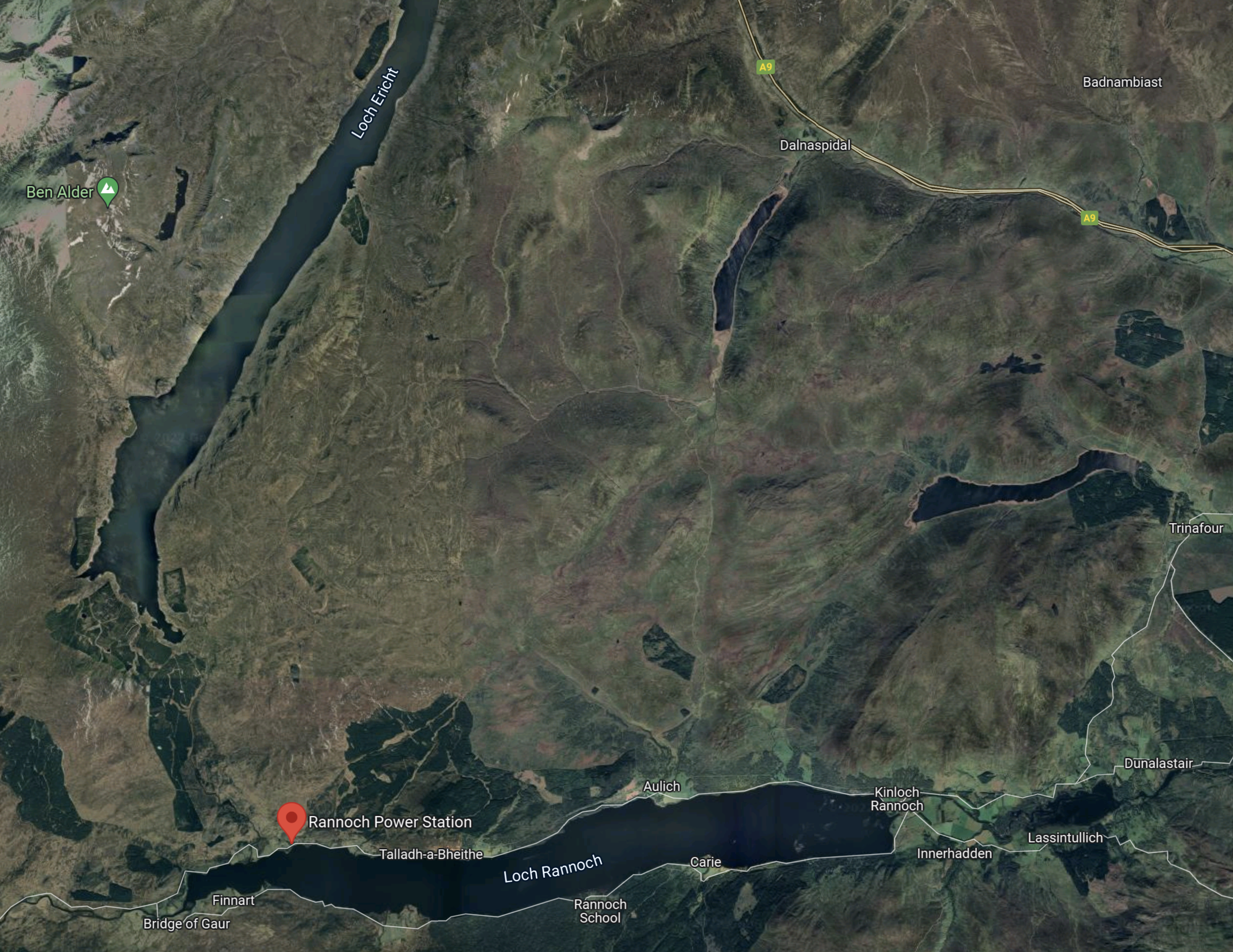
Note.
- Loch Rannoch is along the bottom of the map with Loch Dunalastair to the right.
- Loch Rannoch has an altitude of 205 metres.
- Rannoch power station is indicated by the red arrow.
- Rannoch power station was built in 1930 and the history of the power station is told in this page on the SSE web site, which is entitled A Real Gem In Hydro History.
- Loch Ericht runs to the North from above the power station.
- Loch Ericht has an altitude of 350 metres.
This Google Map shows Rannoch power station to a larger scale.
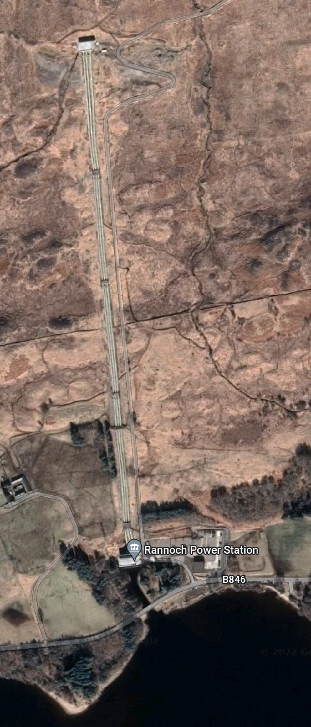
Rannoch power station is on the shore of Loch Rannoch and is described in this section in Wikipedia. This is said.
Rannoch Power Station, on the northern shore of the loch, is part of the Tummel hydro-electric power scheme, which is operated by SSE. The power station has a vertical head of 156 m (512 ft) and a total generating capacity of 44 MW, and uses water fed by pipeline and tunnel from Loch Ericht which is discharged into Loch Rannoch.
There are four pipes running down the hill from Loch Ericht, which deliver water to the power station.
The layout of Rannoch power station seems very similar to Sloy power station, which I described in A Lower-Cost Pumped Hydro Storage System.
- Both power stations sit on a large deep loch.
- Both have pipes to supply water going up the hill and then in a tunnel to a large loch over a hundred metres above the lower reservoir.
- Rannoch power station is a 44 MW power station built in 1930.
- Sloy power station is a 152.5 MW power station built in 1950.
SSE have been examining if a pumped-storage station could be added to Sloy power station.
Given the similarity of the layouts of the two stations, it could be that if it is possible to add pump storage to Sloy, that this could also be done at Rannoch.
Could 41 GWh be stored above Rannoch power station? I won’t say it is not possible.
Conclusion
Research at Strathclyde University gives these figures for possible storage capacity for these dams and lochs in the Tummel scheme.
- Errochty – 16 GWh
- Clunie – 40 GWh
- Rannoch – 41 GWh
- Tummel – 38 GWh
Adding these up gives a total of 135 GWh of stored energy for the Tummel scheme.
But that assumes every power station and dam is expanded to fit Strathclyde’s research.
SSE Renewables are currently calling for tenders for Coire Glas, as I wrote about in SSE Renewables Launches 1.5GW Coire Glas Construction Tender.
This was my conclusion in that post.
It looks to me, that it’s almost certain that Scotland will get a 1.5GW/30 GWh pumped-storage system at Coire Glas.
Coire Glas could supply slightly more power than Sizewell B nuclear power station for twenty hours.
Now that’s what I call backup!
But in the Tummel scheme, there could be three places, where a 30 GWh pumped-storage scheme could be developed and one where a 16 GWh scheme could be developed.
I would expect that a conservative figure of between 40-60 GWh of pumped-storage capacity could be added to the Tummel scheme.
Repurposing The Great Glen Hydro-Electric Scheme
The Great Glen hydro-electric scheme was built in the 1950s and early 1960s, by the North of Scotland Hydroelectric Board.
- The scheme is now owned by SSE Renewables and has a page on their web site.
- There are six individual power stations; Ceannacroc, Livishie, Glenmoriston, Quoich, Invergarry and Mucomir.
- There are five dams; Cluanie, Loyne, Dundreggan, Quoich and Invergarry.
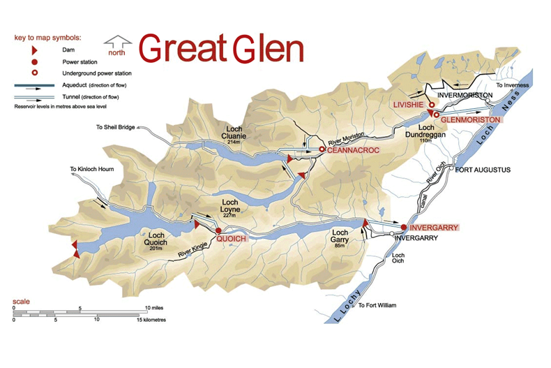
This map from the SSE Renewables web site shows the layout of the dams and power stations.
The sizes of the power stations in the scheme are as follows.
- Ceannacroc – 20 MW
- Livishie – 15 MW
- Glenmoriston- 37 MW
- Quoich – 18 MW
- Invergarry – 20 MW
- Mucomir – 1.7 MW
This gives a total power of 112.7 MW.
This Google Map shows the same area as the SSE Renewables Map.
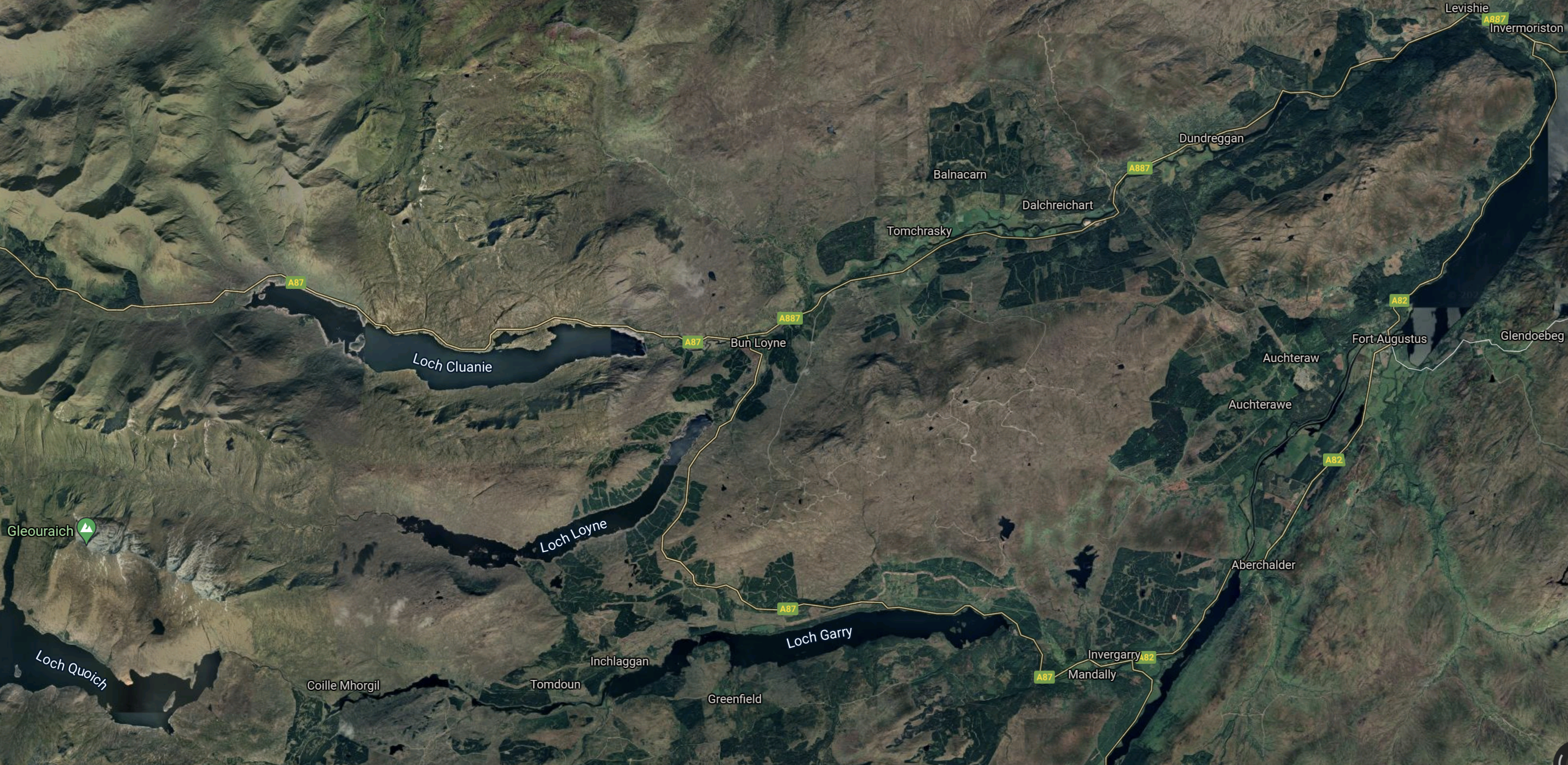
Note.
- Loch Quoich is in the South-West corner.
- To the East of Loch Quoich is Loch Garry and to the North-East is Loch Loyne.
- Loch Cluanie is to the North.
- Invermoriston is in the North-East corner.
The scheme also includes three underground power stations and several miles of tunnels.
Strathclyde University And Pumped Storage Power For Scotland
This page on the Strathclyde University gives a list of the pumped storage potential for Scottish hydrogen-electric dams and power stations.
These figures are given for the dams and lochs in the Great Glen scheme.
- Invergarry – 22 GWh
- Glenmoriston- 41 GWh
- Quoich – 27 GWh
It would appear that based on research from Strathclyde University, that the Great Glen scheme could support up to 90 GWh of pumped storage.
Water Flows In The Great Glen Scheme
Looking at the SSE Renewables map of the Great Glen scheme, water flows appear to be as follows.
- Loch Quoich to Loch Garry via Quoich power station.
- Loch Garry to Loch Oich via Invergarry power station.
- Loch Loyne to Loch Dundreggan via River Moriston.
- Loch Cluanie to Loch Dundreggan via Ceannacroc power station and River Moriston.
- Loch Dundreggan to Loch Ness via Glenmoriston power station.
All the water eventually flows into the sea at Inverness.
Refurbishing And Repurposing The Great Glen Scheme
Perhaps as the power stations are now over fifty years old, one simple way to increase the generating capacity of the Great Glen scheme, might be to selectively replace the turbines, with modern turbines, that can generate electricity more efficiently.
I suspect that SSE Renewables have an ongoing program of improvements and replacements for all of their hydro-electric stations in Scotland. Some turbines at Sloy power station have already been replaced with larger ones.
Adding Pumped Storage To The Great Glen Scheme
I would assume that the water to pump uphill at night or when there is a surplus of electricity will come from Loch Oich or Loch Ness.
Some power stations like Glenmoriston and Invergarry might be updated to both generate electricity or pump water up hill, as is required.
Conclusion
There would appear to be up to three schemes, that could each add around 30 GWh of pumped storage.
One advantage is that the waters of Loch Ness can be used for the lower reservoir.
Repurposing The Affric/Beauly Hydro-Electric Scheme
The Affric/Beauly hydro-electric scheme was built in the 1950s and early 1960s, by the North of Scotland Hydroelectric Board.
- The scheme is now owned by SSE Renewables and has a page on their web site.
- There are six individual power stations; Mullardoch, Fasnakyle, Deanie, Culligran, Aigas and Kilmorack.
- There are seven dams; Mullardoch, Benevean, Monar, Loichel, Beannacharan, Aigas and Kilmorack.
This map from the SSE Renewables web site shows the layout of the dams and power stations.
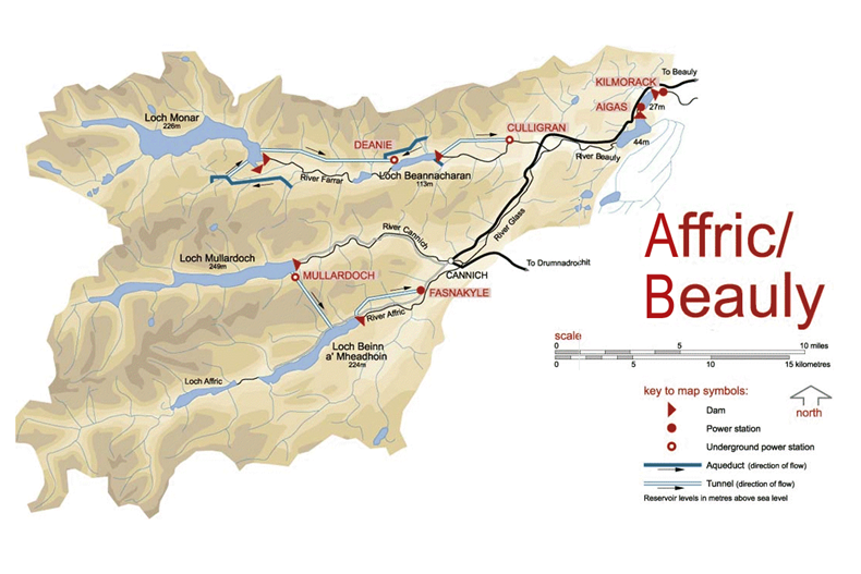
This description of the scheme is from Wikipedia.
The Affric / Beauly hydro-electric power scheme for the generation of hydro-electric power is located in the western Highlands of Scotland. It is based around Glen Strathfarrar, Glen Cannich and Glen Affric, and Strathglass further downstream.
The scheme was developed by the North of Scotland Hydro-Electric Board, with plans being approved in 1947.
The largest dam of the scheme is at Loch Mullardoch, at the head of Glen Cannich. From there, a tunnel takes water to Loch Beinn a’ Mheadhoinn (Loch Benevean) in Glen Affric, via a small underground power station near Mullardoch dam. Loch Benevean is also dammed, with a tunnel taking water to the main power station of Fasnakyle, near Cannich.
To the north in Glen Strathfarrar, Loch Monar is dammed, and a 9 km tunnel carries water to an underground power station at Deanie. Further down the glen, the River Farrar is dammed just below Loch Beannacharan, with a tunnel to take water to Culligran power station (also underground).
The River Farrar joins with the River Glass near Struy to form the River Beauly. Downstream on the River Beauly, dams and power stations have been built in gorges at Aigas and Kilmorack.
As the rivers in this scheme are important for Atlantic salmon, flow in the rivers is kept above agreed levels. The dams at Kilmorack, Aigas and Beannacharn contain Borland fish lifts to allow salmon to pass.
Note
- Culligran, Deanie and Mullardoch power stations are underground.
- Loch Beannacharan is the English name for Loch Beinn a’ Mheadhoin.
- The salmon impose a constraint on water levels.
The sizes of the power stations in the scheme are as follows.
- Mullardoch – 2.4 MW
- Fasnakyle – 69 MW
- Deanie – 38 MW
- Culligran – 19 MW
- Aigas – 20 MW
- Kilmorack – 20 MW
This gives a total power of 168.4 MW.
This Google Map shows the Western area of the SSE Renewables Map.
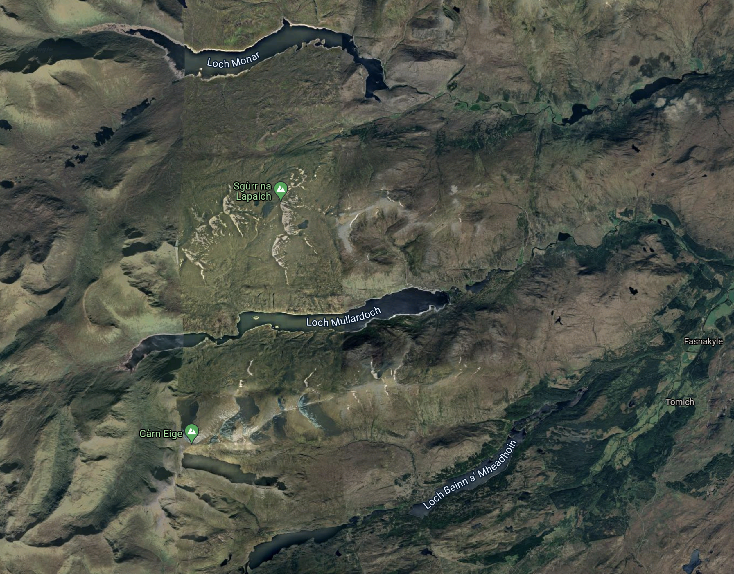
Note.
- The three lochs; Monar, Mullardoch and Beinn a’ Mheadhoin can be picked out on both maps.
- Fasnakyle, where the largest of the hydro-electric power stations in the Affric/Beauly scheme, is at the Eastern edge of the map about half-way up.
- The area doesn’t seem to have a large population.
This Google Map shows the location of Fasnakyle power station in more detail.
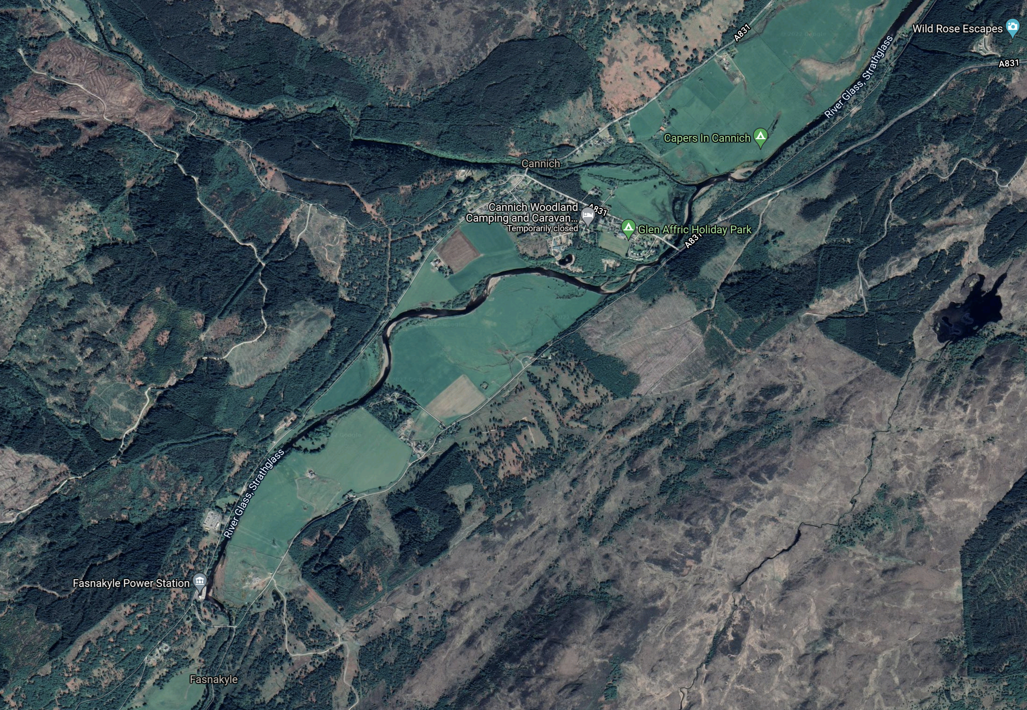
Note.
- Fasnakyle power station is in the South-West corner of the map. marked by a grey flag.
- It appears that all of the water that goes through the power station flows into the River Glass, Strathglass, which meanders its way towards Inverness on the bottom of what appears to be a broad valley.
This Google Map shows the next section of the river.
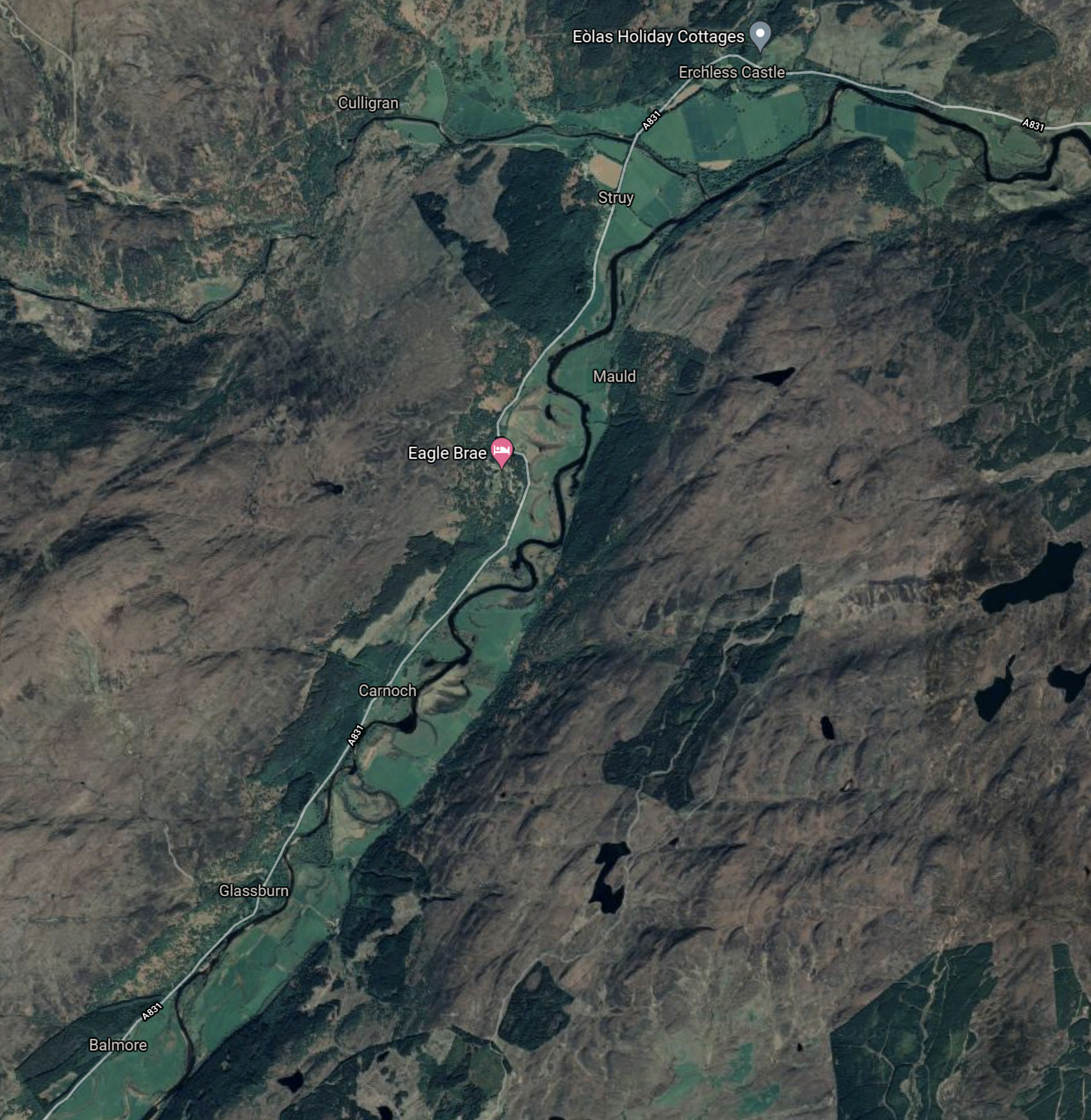
The River Glass, Strathglass joins the River Farrar near the top of the map an becomes the River Beauly.
This Google Map the River Beauly to Kilmorack.
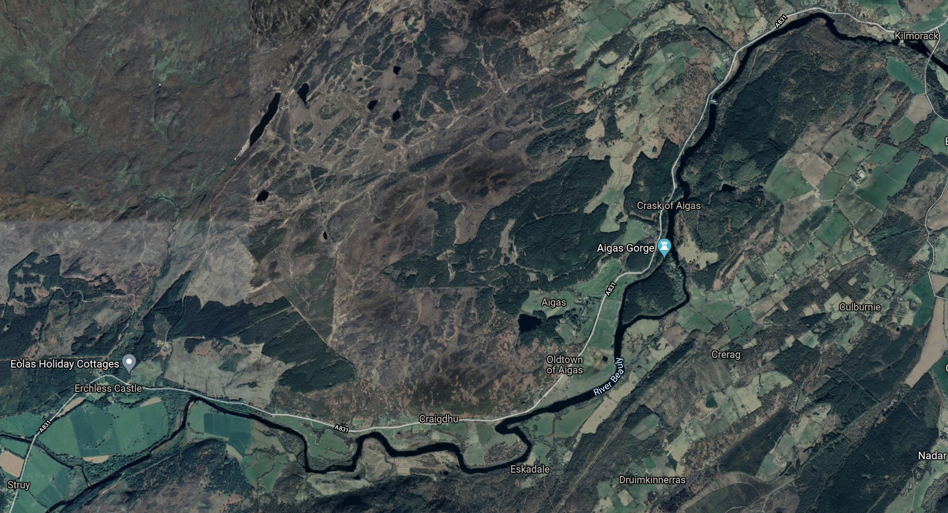
Wikipedia says this about this section of the River Beauly.
The river is part of the Affric-Beauly hydro-electric power scheme, with dams and power stations at Aigas and Kilmorack. Both have 20MW generators and include fish ladders to allow salmon to pass, the Aigas fish ladder is open to visitors in the summer.
This last Google Map shows the Beauly Firth.
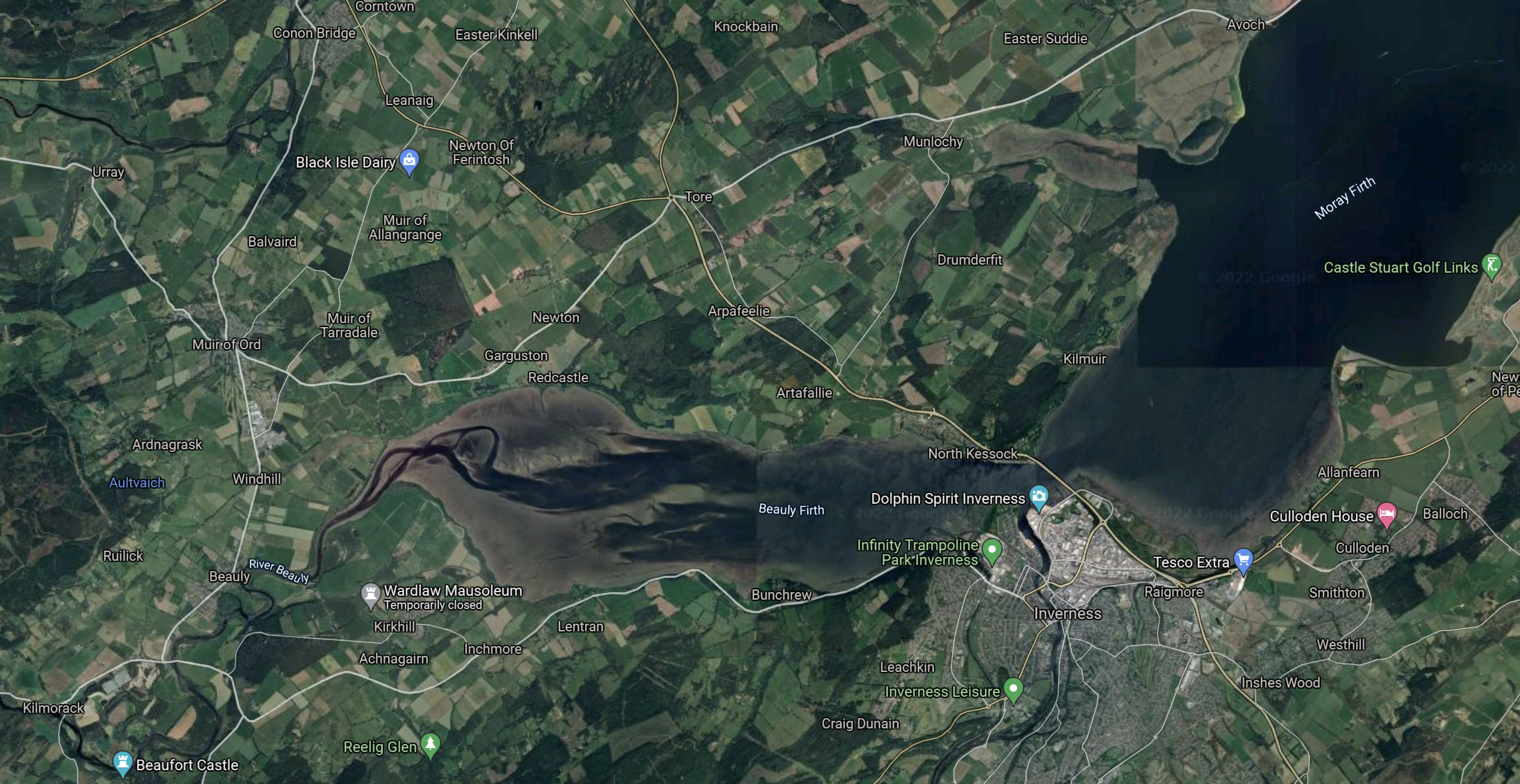
Note.
- Kilmorack is in the South-West corner of the map.
- The River Beauly flows into the Beauly Firth and ultimately out to see in the Moray Firth.
- The water flows past Inverness to the North.
It does strike me, that a lot of the water collected in the dams to the West of Fasnakyle, flows out to sea.
Strathclyde University And Pumped Storage Power For Scotland
This page on the Strathclyde University gives a list of the pumped storage potential for Scottish hydrogen-electric dams and power stations.
A figure is given for only one dam or power station in the Affric/Beauly scheme.
- Fasnakyle – 78 GWh
That would be a lot of pumped storage.
Water Flows In The Affric/Beauly Scheme
Looking at the SSE Renewables map of the Conon scheme, water flows appear to be as follows.
- Loch Monar to Loch Beannacharan via Deanie power station
- Loch Beannacharan to River Beauly via Culligran power station
- Lochs Mullardoch and Beinn a’ Mheadhoin both supply water to the Fasnakyle power station
- Fasnakyle power station to River Beauly via the River Glass, Strathglass.
- River Beauly to Beauly Firth via Aigas and Kilmorack power stations.
Note.
- Water from Loch Moray goes via Deanie , Culligran, Aigas and Kilmorack power stations on its journey to the sea.
- Water from Loch Mullardoch goes via Mullardoch , Fasnakyle, Aigas and Kilmorack power stations on its journey to the sea.
- Water from Loch Beinn a’ Mheadhoin goes via Fasnakyle, Aigas and Kilmorack power stations on its journey to the sea.
Fasnakyle, Aigas and Kilmorack power stations must work very hard.
Refurbishing And Repurposing The Affric/Beauly Scheme
Perhaps as the power stations are now over fifty years old, one simple way to increase the generating capacity of the Affric/Beauly scheme might be to selectively replace the turbines, with modern turbines, that can generate electricity more efficiently.
I suspect that SSE Renewables have an ongoing program of improvements and replacements for all of their hydro-electric stations in Scotland. Some turbines at Sloy power station have already been replaced with larger ones.
I also suspect that the whole scheme has a very sophisticated control system.
Consider.
- There is a need to control water levels to agreed minimum levels for the Atlantic salmon.
- Hydro-electric power stations have the ability to get to full power quickly, to cover sudden demands for more electricity.
- Electricity only needs to be generated if it can be used.
- Water might be held in Lochs Mullardoch and Beinn a’ Mheadhoin, as a reserve, as it goes through three or four power stations when it is released.
Over the years, SSE Renewables will have developed very sophisticated control philosophies.
Adding Pumped Storage To The Affric/Beauly Scheme
To do this a source of fresh-water must be pumped into Loch Mullardoch or Beinn a’ Mheadhoin, when there is a surplus of electricity.
It looks from Google Maps, that the river system between Fasnakyle and Aigas power stations has been effectively turned into a canal.
- I wonder, if it is deep enough to contain enough water to act as the lower level reservoir of a pumped-storage system.
- The higher level reservoir would be Loch Mullardoch.
- There would be a height difference of 200 metres.
- Calculations show around 1850 cubic metres of water would need to be pumped into Loch Mullardoch to store one MWh.
So long as enough water is left for the salmon, I suspect that if a way of pumping water from the River Glass to Loch Mullardoch, that an amount of pumped-storage can be added.
Conclusion
There would appear to be only one scheme, but if it was built it could add over 50 GWh of pumped storage.
Repurposing The Conon Hydro-Electric Scheme
The Conon hydro-electric scheme was built in the 1950s, by the North of Scotland Hydroelectric Board.
- The scheme is now owned by SSE Renewables and has a page on their web site.
- There are six individual power stations; Achanalt, Grudie Bridge, Mossford, Luichart, Orrin and Torr Achilty.
- There are six dams; Glascarnoch, Vaich, Luichart, Meig, Torr Achilty and Orrin.
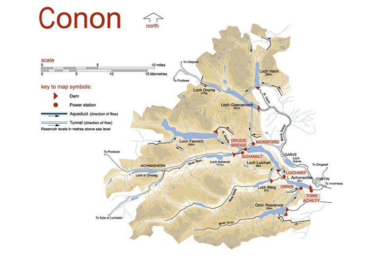
This map from the SSE Renewables web site shows the layout of the dams and power stations.
The sizes of the power stations in the scheme are as follows.
- Achanalt – 3 MW
- Grudie Bridge – 18.6 MW
- Mossford – 18.6 MW
- Luichart – 34 MW
- Orrin – 18 MW
- Torr Achilty – 15 MW
This gives a total power of 107.2 MW.
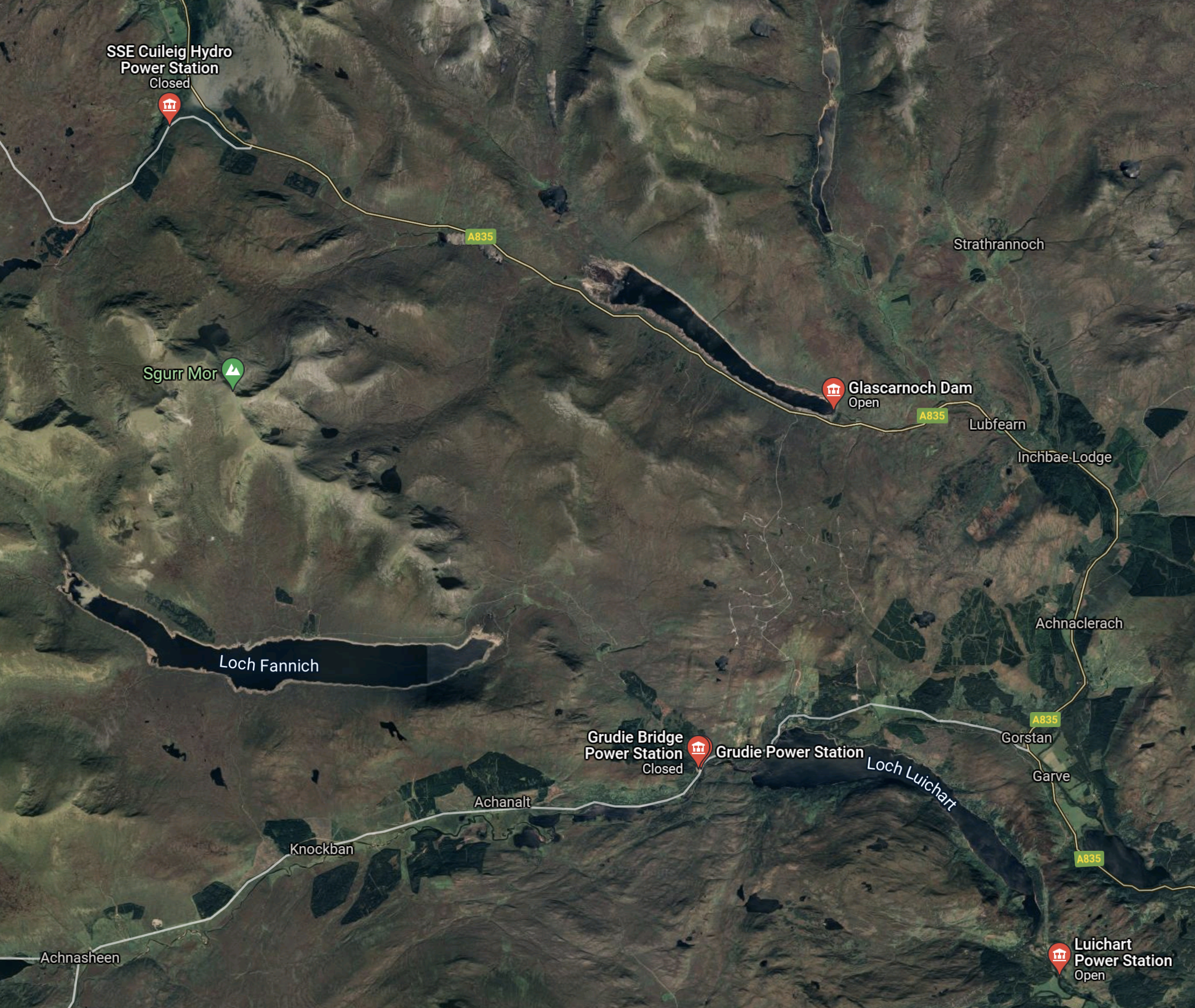
This Google Map shows the same area as the SSE Renewables Map.
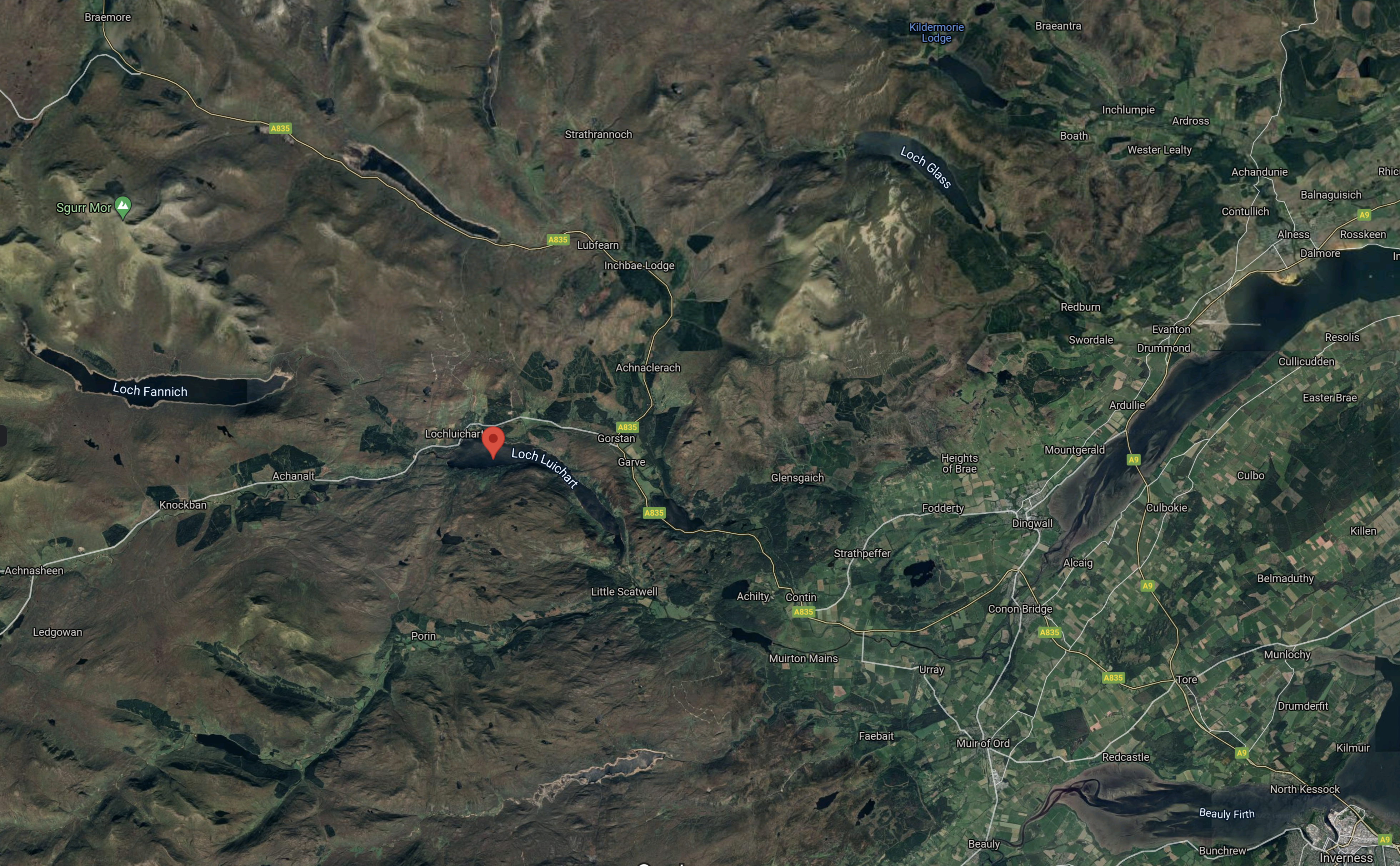
Note.
- Inverness is in the South-East corner of the map.
- The red arrow indicates the Western end of Loch Luichart.
- Loch Fannich is the large loch to the West of Loch Luichart.
- Loch Glascarnoch is the East-West loch to the North of Loch Luichart
- Loch Vaich is the North-South loch to the North of Loch Glascarnoch.
Is Inverness a City substantially powered by renewables?
Strathclyde University And Pumped Storage Power For Scotland
This page on the Strathclyde University gives a list of the pumped storage potential for Scottish hydrogen-electric dams and power stations.
These figures are given for the dams and lochs in the Conon scheme.
- Glascarnoch – 23 GWh
- Luichart – 38 GWh
- Fannich – 70 GWh
It would appear that based on research from Strathclyde University, that the Conon scheme could support up to 131 GWh of pumped storage.
This Google Map shows the three lochs and Loch Vaich.
Note.
- Lochs Fannich and Luichart are named.
- Loch Glascarnoch is the East-West loch to the North of Loch Luichart
- Loch Vaich is the North-South loch to the North of Loch Glascarnoch.
- The locations of several power stations are shown.
- Cuileig is a 3.2 MW power station built in 2002.
This Google Map shows Loch Fannich.
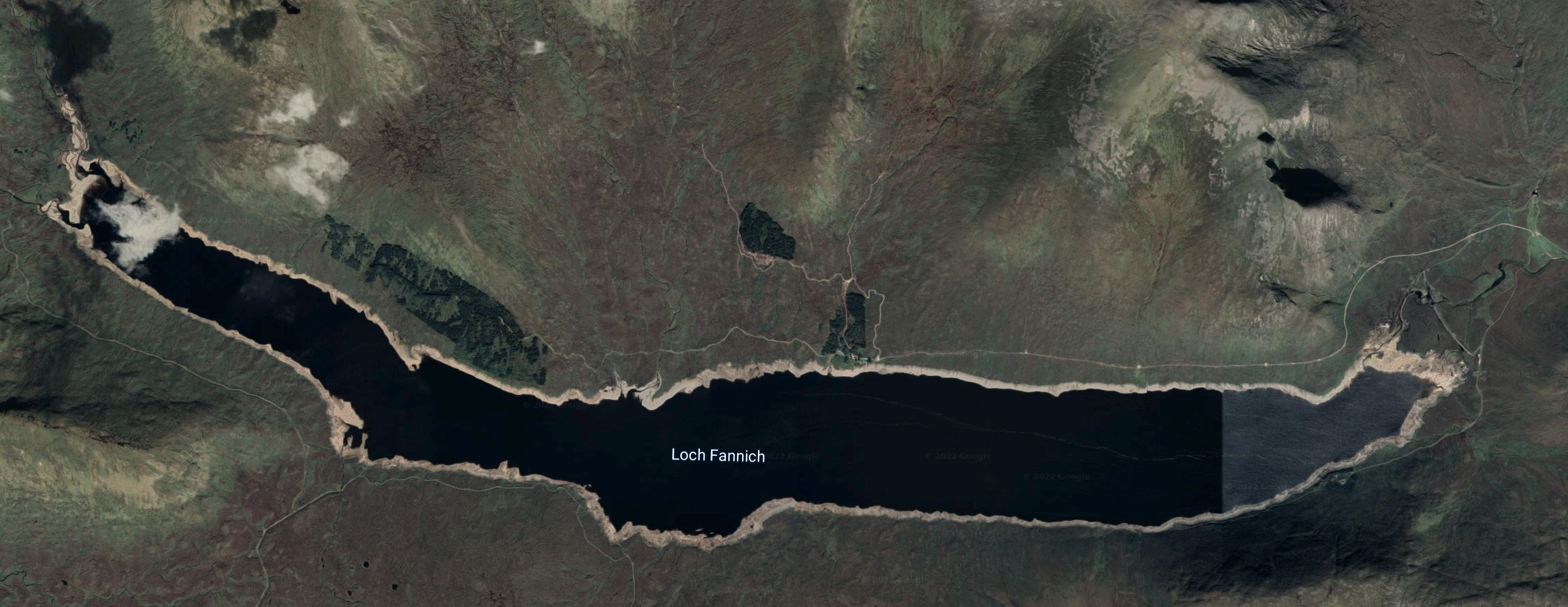
Wikipedia says this about the loch.
Loch Fannich was dammed and its water level raised as part of the Conon Hydro-Electric Power Scheme, built by the North of Scotland Hydro-Electric Board between 1946 and 1961. An underground water tunnel leading from Loch Fannich to the Grudie Bridge Power Station required blasting out a final mass of rock beneath the loch, a procedure which was referred to popularly as “Operation Bathplug”.
The dam appears to be at the Eastern end of the loch, as this Google Map shows.
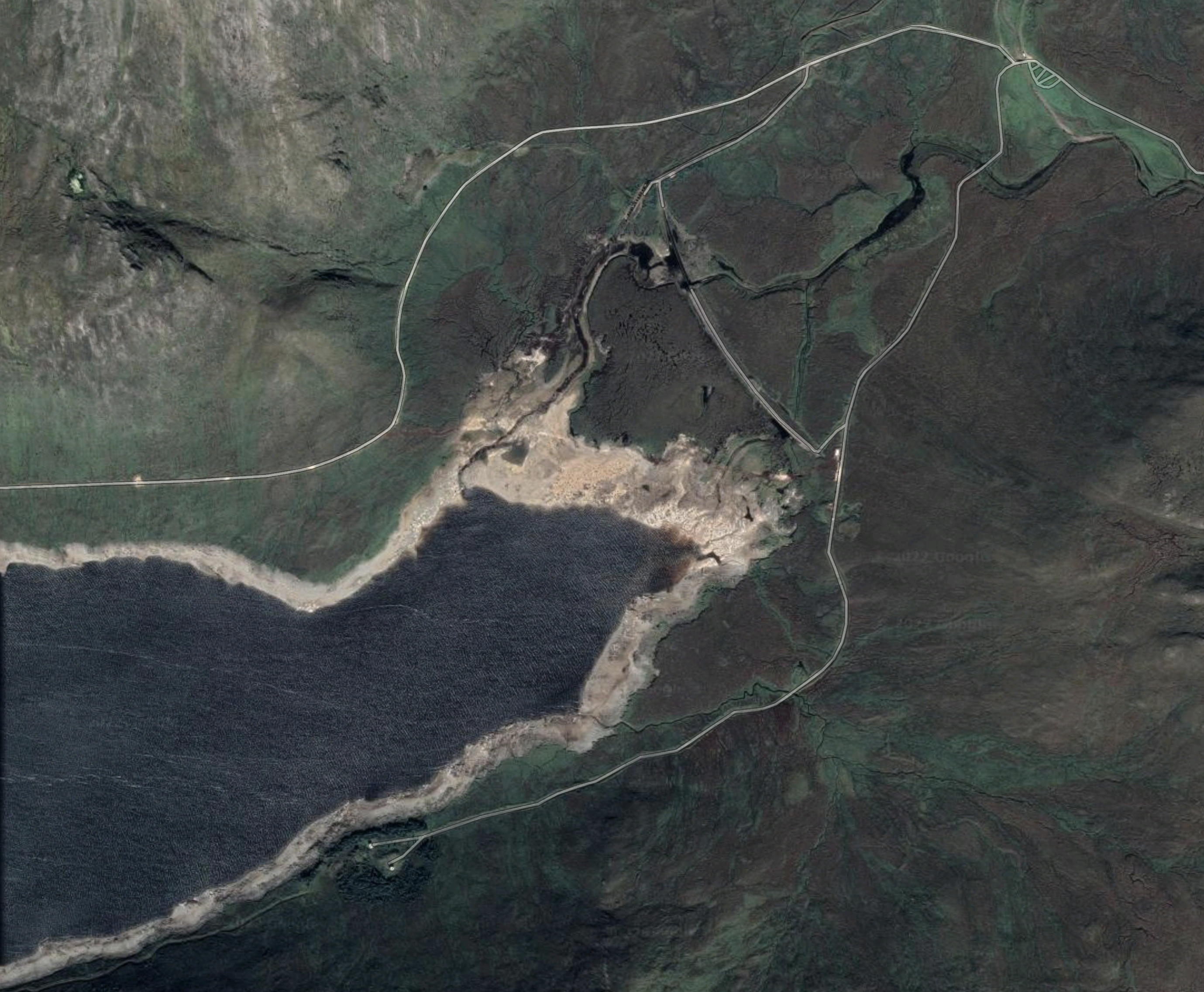
I wouldn’t be surprised to find that to obtain the potential 70 GWh of storage, that the dam will need to be raised.
This Google Map shows Loch Glascarnoch.
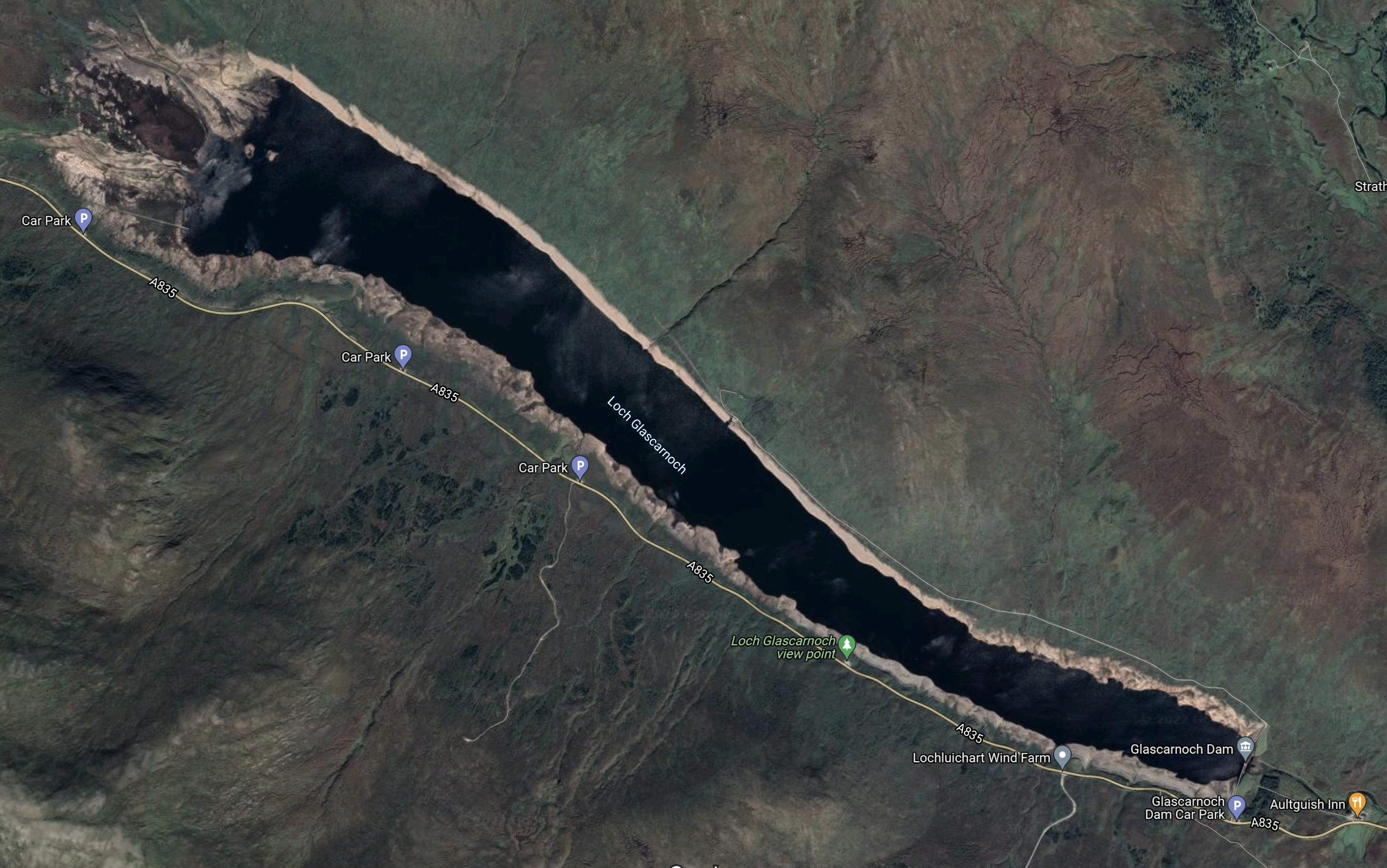
Loch Glascarnoch may be more difficult to expand, as a road runs along the Southern side of the loch.
This Google Map shows Loch Luichart
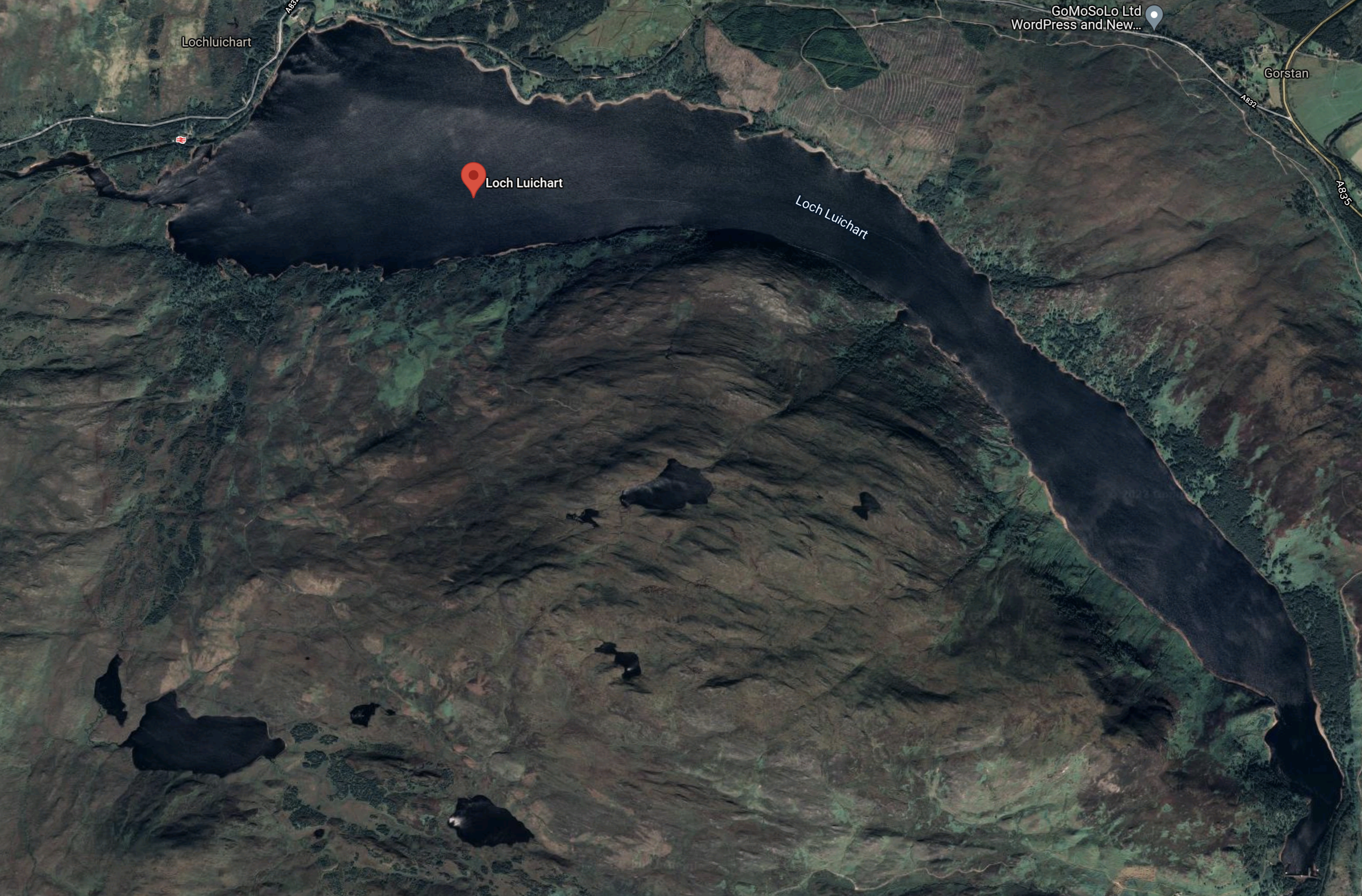
Lock Luichart may have possibilities as it is wide and could be deep.
But it will all be about the shape of the loch and the mathematics of the water.
Water Flows In The Conon Scheme
Looking at the SSE Renewables map of the Conon scheme, water flows appear to be as follows.
- Loch Vaich to Loch Glascornoch
- Loch Droma to Loch Glascornoch
- Loch Glascornoch to Loch Luichart via Mossford power station
- Loch Fannich to Loch Luichart via Grudie Bridge power station
- Loch Achanalt to Loch Luichart via Anchanalt power station
- Loch Meig to Loch Luichart
- Loch Luichart to Loch Achonachie via Luichart power station
- Orrin Reservoir to Loch Achonachie via Orrin power station
- Loch Achonachie to River Conon and eventually the Cromarty Firth via Torr Achilty power station
Note that all the power stations date from the 1950s.
Repurposing The Conon Scheme
Perhaps as the power stations are now over sixty years old, one simpler way to both increase the generating capacity of the Conon scheme and add a degree of pumped storage might be to selectively replace the turbines, with modern pump/turbines, that can both generate electricity and pump the water back up into the mountains.
It should also be noted that Loch Vaich, Loch Glascornoch, Loch Fannich and the Orrin Reservoir are all about 250 metres above sea level, with the others as follows.
- Loch Achanalt – 111 metres
- Loch Luichart – 56 metres
- Loch Meig – 87 metres
- Loch Achonachie – 30 metres
Loch Droma is the highest loch at 270 metres.
These height differences could create opportunities to put in extra tunnels and power or pumping stations between the various levels.
As water pumped to a greater height has a higher potential energy, perhaps it would be an idea to give Loch Droma, which is the highest loch, a bigger role.
Conclusion
I believe these improvements are possible.
- Adding a pumped storage facility to the Conon hydro-electric scheme, with a capacity of upwards of 30-40 GWh.
- Increasing the generating capacity by replacing the elderly turbines.
- Improving control of the scheme, by replacing 1950s control systems.
It may even be possible to substantially improve the performance of the scheme without any expensive rock tunnelling.
Fracking Has a Bad Rep, but Its Tech Is Powering A Clean Energy Shift
The title of this post, is the same as that of this article on Texas Monthly.
It shows how former frackers are developing their techniques to do the following.
- Extract heat and energy from shale using water.
- Store energy safely underground.
- Drill deeper and better geothermal wells.
One of the companies; Quidnet has been backed by Bill Gates and his friends. I wrote about Quidnet Energy a couple of years ago in How Do You Save Clean Energy? This Company Plans To Pump It Underground.
And all in environmentally-friendly ways, that would get a seal-of-approval from a committed anti-fracker.
It’s the best article I’ve read this week.
The Development Of The Foyers Pumped Storage Scheme
This leaflet from SSE Renewables probably gives as good a record as any others about the development of the Foyers Pumped Storage Scheme.
This is the introduction.
The Foyers Scheme is a 300 Megawatt (MW) combined conventional hydro and pumped storage scheme. 1896 saw the British Aluminium Company commission Foyers for the smelting of aluminium. The plant was in continuous operation for 70 years until it’s closure in 1967. The scheme was promoted by NOSHEB in February 1968 and after receiving statutory approval in April 1969 work started that autumn and was commissioned in 1975 . The high level reservoir is Loch Mhor which was formed under the original development by enlarging and joining Loch Garth and Loch Farraline.
The full catchment area of Loch Mhòr today is now 207 sq km.
Note that NOSHEB stands for North of Scotland Hydro Electric Board.
This Google Map shows Loch Mhòr.
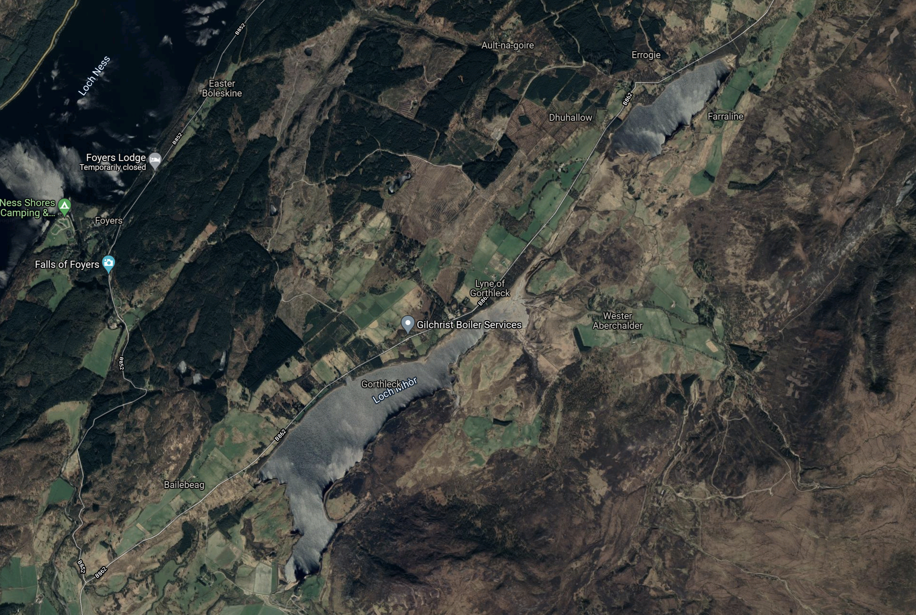
Note.
- Loch Ness is in the North West corner of the map.
- Loch Mhòr is the loch running diagonally across the map.
- Loch Mhòr was originally two separate lochs; Loch Garth in the South-West and Loch Farraline in the North-East.
- The power station is on the shores of Loch Ness.
I have found a document on the Internet, that says that the current storage capacity of Loch Mhòr is 10 GWh. That figure, if it is correct, would make the Foyers pumped storage scheme a small amount bigger than Electric Mountain.
The Original Scheme
The original scheme appears to have been a straight hydro-electric scheme with the water running from Loch Mhòr into Loch Ness through turbines. I don’t know how big it was and if anybody does, the figure needs to be inserted in this post. So if you know it, please tell me!
This gazetteer gives the figure at 3750 kW and also this history.
The British Aluminum Company development at Foyers was the first large-scale use of hydropower in Scotland. The scheme was highly influential, proving not only the viability of the technology to produce electricity with water driven turbines, but also that the power could be successfully applied to industrial processes. The British Aluminum Company went on to develop two large smelters in Scotland at Kinlochleven and Lochaber.
The original scheme generated electricity for seventy years.
The Current Scheme
There are effectively two parts of the current scheme, which was created in the early 1970s.
- The original 3.7 MW turbines have been replaced by a 5 MW turbine in the old power station.
- A new separate pumped storage power station has been built with two 150 MW pump/turbines.
This paragraph from the leaflet from SSE Renewables, gives brief details of the engineering.
When the station is generating, water flows from Loch Mhor through 2 miles of tunnels and shafts to the power station. When pumping, energy is drawn from the main transmission system at times of low load to drive the two 150 megawatt machines in the reverse direction and pump water from Loch Ness up to Loch Mhor. The existing gravity dam at the outlet of Loch Mhor (231.7m long and 9.14m high) was retained by NOSHEB . Remedial work was carried out on subsidiary earth embankment dams. The waters of the River Fechlin are diverted into Loch Mhor by a tunnel and the channel of the river.
From the complete description in the leaflet, it looks to be sound engineering.
Did Modern Project Management Enable This Scheme?
As someone, who was involved in writing project management software from about 1972, I do wonder if the arrival of ,odern project management around the mid-1960s was one of factors that prompted NOSHEB to carry out this scheme.
Other factors would have been.
- The original turbines were on their last legs after seventy years of generating electricity.
- There was a need for more pumped storage.
- This scheme was feasible.
I would very much like to meet one of the engineers and talk the scheme through.
Conclusion
This power station and its rebuilding as a pumped storage scheme has been carried out to an excellent standard and I wonder if similar techniques can be used to create new pumped storage systems around the world.
Glendoe Hydro Power Station
When I think of hydro-electric power stations in the UK, I generally, think that most of the hydro-electric power stations were built years ago by organisations like the North of Scotland Hydroelectric Board. These power stations were one of the staples of the Meccano Magazine, of which I was a long-term subscriber in the 1950s.
But Glendoe hydro-electric power station is relatively new having been opened in 2009. At only 100 MW, the power-station may not be large in comparison to others around the world, but it does show what can be built in the Highlands of Scotland.
This Google Map shows the layout of the power station.
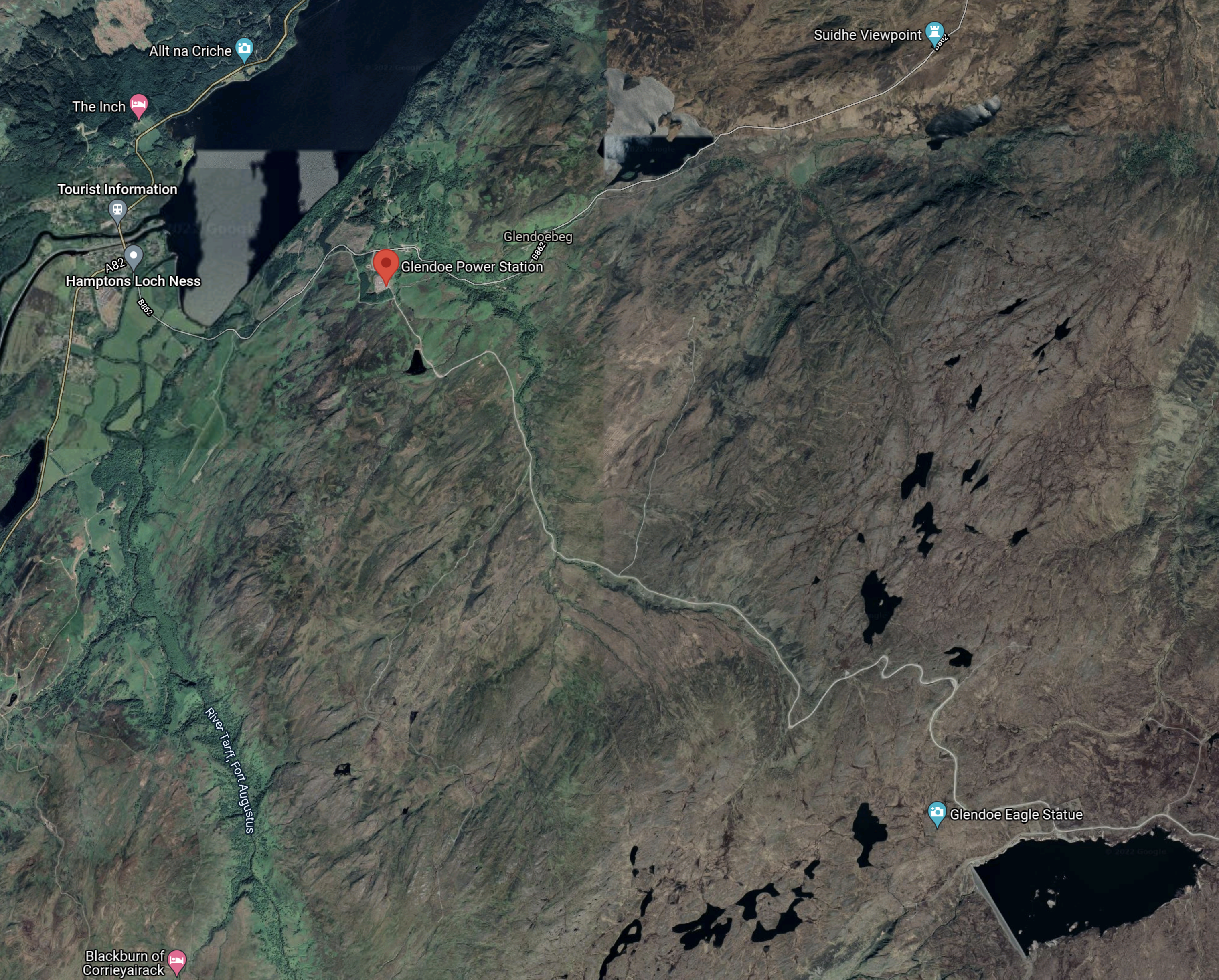
Note.
- The red arrow indicates the location of Glencoe power station, which is underground.
- To the North of the power station, is the Southern end of Loch Ness.
- In the South-Eastern corner of the map there is the lake from which the power station draws its water.
- The dam is at the Western end of the lake.
According to this article on Power Technology, the project cost £160 million.
This extract from a page on the SSE Renewables web site, describes the layout of the tunnels and the operation of the power station.
Engineers began planning the Glendoe project as far back as October 2001. Formal construction work at the site started over four years later, in January 2006. It involved constructing a 960 metre-wide dam on the River Tarff to create a new reservoir some 600 metres above the power station, giving it the greatest head of any hydro electric power station in the UK.
An 8.6 kilometre tunnel connects the reservoir to the power station that is built 250 metres below ground level, about two kilometres from the banks of Loch Ness. Although some of the tunnel was created using traditional drill and blast techniques that would have been familiar to the Tunnel Tigers of the last century, much of its length was bored out using a massive tunnelling machine named Eliza Jane by local schoolchildren.
The SSE page also describes the working and living conditions of those who built the scheme.
Most lived in specially constructed camps high in the hills above Loch Ness, braving brutal weather conditions in winter, and the fearsome Scottish midges in the summer.
The SSE page also gives the main use of the power station.
Today, the main operating feature of Glendoe is its ability to react quickly to changing demand for electricity, being able to reach full output in just 90 seconds.
So when there is an important football or rugby match on the television, it is ideal to supply the surge of electricity, when everybody puts on the kettle at half time.
Could This Power Station Have A Pumped Storage System Added?
Consider.
- There is a large lake six hundred metres above the power station.
- Loch Ness is a large source of water at the bottom of the mountain.
- Every tonne or cubic metre of water pumped into the upper lake would store 1.63 kWh of electricity.
- The world’s and the UK’s tunneling engineers are getting better and more ambitious.
- When this power station was built in the early years of this century, there wasn’t the large amount of wind turbines in Scotland, that there are now.
I suspect, it’s an idea that’s been looked at, but the costs or the distance to pump the water might kill it.
If a second project was the same size as the first, it would cost £210 million based on inflation.
But.
- It wouldn’t need another dam or a substation to connect to the National Grid.
- There would probably be a need for extra excavation at the power station to put in the pumps.
- I suspect it would need an extra tunnel to get the water uphill.
- One tunneling engineer told me, as with sex, digging a second tunnel is easier.
The main benefit, would be that it would be hidden infrastructure.
As to the energy storage capacity, I estimate from maps that the top reservoir at Glendoe is about half the size of Loch Mohr at Foyers power station, but the head is 600 metres as against 197 metres. As Foyers can store 10 GWh, it looks to me, that Glendoe could store around 15 GWh.
Also, as Glendoe power station was designed and built after the successful conversion of Foyers to a pumped storage station, I wouldn’t be surprised to find that Glendoe was designed, so that the station could be converted to pumped storage at a later date.
Conclusion
This scheme will be seriously looked at for extension with a pumped storage facility.
Offshore Service Facilities
Some years ago at a wedding in The Netherlands, I got talking to a Dutch engineer, who had a lot to do with the creation of the Delta Works.
Also in The Netherlands, I visited the Watersnoodmuseum, which describes the floods in the Netherlands, that brought about the Delta Works.
So I was not surprised to see the spectacular offshore construction ideas talked about on the Offshore Service Facilities web site.
The site talks about a project to create a four GW wind farm, eighty kilometres off the coast, all serviced from an artificial island.
This is their overview of what they call the IJVER project.
IJmuiden Ver (IJVER) is one of the designated wind farm areas under the Dutch offshore wind road map 2030. With a capacity of at least 4 GW and a distance to shore of approximately 80 km, it is currently the largest foreseen Dutch wind farm zone, and the furthest from shore. The area also includes legacy oil & gas asset, including several gas pipelines that can be retrofitted to transport other gasses such as hydrogen or for CCS-purposes.
Note.
- 80 km. is not far offshore, when you consider the UK’s Dogger Bank C wind farm is 196 km from Teesside.
- There are depleted gas fields for storage and pipelines to transport gases to and from the shore.
This page describes the concept, starting with this introductory paragraph.
A multi-purpose island provides additional benefits over fixed offshore platforms (so-called jackets). It stimulates the energy transition, drives down the costs of the renewable energy transition, creates room for nature inclusive island design, facilitates Research & Development (R&D) and innovation, creates a safe working environment, as well as additional economic opportunities.
One feature they are proposing is an interconnector to the UK.
In Is There A Need For A Norfolk-Suffolk Interconnector?, I suggested that Bacton, Sizewell and Felixstowe could be places, where wind power from the North Sea were to be landed.
Distances to the IJVER island would be as follows.
- Bacton – 85 miles
- Sizewell – 77 miles
- Felixstowe – 92 miles
These distances are feasible for an interconnector.
There is this explanatory video.
Conclusion
My experience of the Dutch, their civil and marine engineers and their creations, indicates to me, that the Dutch could build an island like this.
Once you have built the island and it can stand up to the weather, you could of course fit it out how you want. Even with a football pitch, as shown in the video.
As with many ideas, the realisation of this concept will depend on the costs involved.
It should be noted, that some UK wind farms have been built with offshore substations, but nothing appears to be as ambitious as this idea and is probably based on proven oil and gas platform technology.
The Dutch also have plans with the Germans and the Danes to create the North Sea Wind Power Hub in the middle of the North Sea.
- This would probably connect to the UK’s Dogger Bank wind farms.
- It would feed electricity as required to the countries around the North Sea.
- Hydrogen could be created on the hub.
- Over a hundred GW of electricity could be generated according to some forecasts.
I like the concept of the North Sea Wind Power Hub and suspect that the Dutch will see it built.
Fortescue Buys Williams Engineering In Major Push Into High Performance Batteries
The title of this post, is the same as that of this article on Renew Economy.
This is the opening paragraph.
Fortescue Future Industries has made its first major push into battery storage and high performance batteries with the $A310 million purchase of Williams Advanced Engineering (WAE), the offshoot of the Formula 1 specialists Williams Grand Prix Engineering.
Andrew Forrest certainly has a wide-ranging plan.
This article on Railway Gazette is entitled Formula 1 Technology Company To Support Development Of Battery Train, was published later and gives more details.
This is the first paragraph.
Fortescue Metals Group’s green technology division Fortescue Future Industries is developing what it says is a ‘world leading’ battery electric train concept.
It will be interesting to see what technologies are at the heart of the ‘world leading’ concept.
If you are controlling a complex chemical or nuclear plant, you will often have a model of the plant inside the control system, so that the operating strategy can be consistently optimised.
I wouldn’t be surprised to see techniques like this and other advanced techniques be used to reduce the carbon footprint of rail transportation of iron ore and other minerals.
Perhaps, the ideal power for one of these heavy haul trains would consist of a master battery-electric locomotive up front with the crew, assisted by up to three hydrogen-, diesel- or battery-powered slaves.
- All braking would be regenerative to battery.
- Power would be called for from the slave locomotives as required.
- Modelling would determine, if some sections needed electrification to charge the batteries.
I suspect there are opportunities to optimise round trips, as returning the empties will surely need less power.
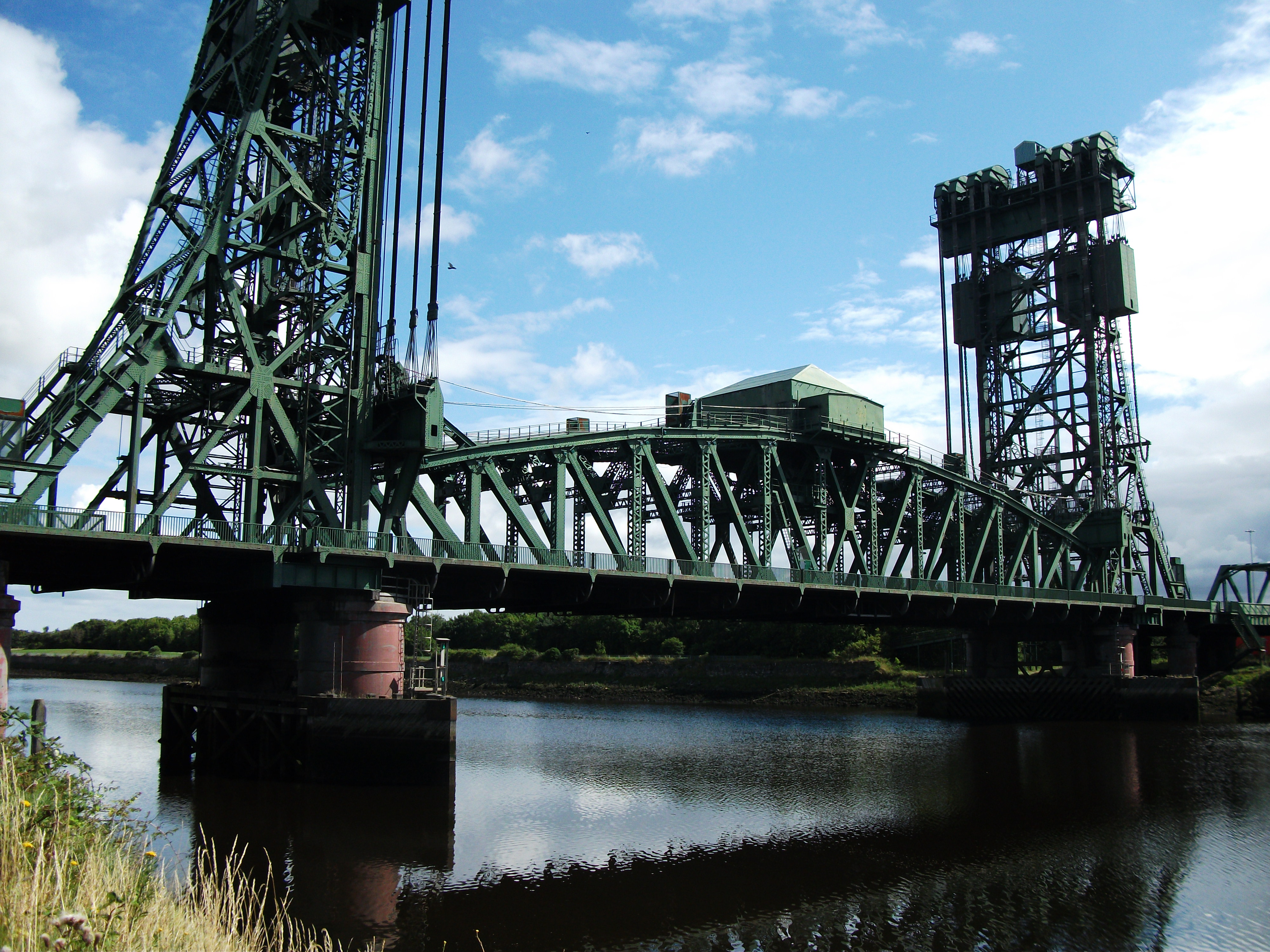
Tees Newport Bridge – 16th December 2021
My train from Middlesbrough To Huddersfield passed the Tees Newport Bridge.


Notice that it is a different colour in this picture from 2010.
The Newport Lifting Bridge
In The Tees Bridges and Barrage, I wrote about Middlesbrough’s bridges.
