Are Crossrail’s Turnback Sidings At Westbourne Park Without Electrification?
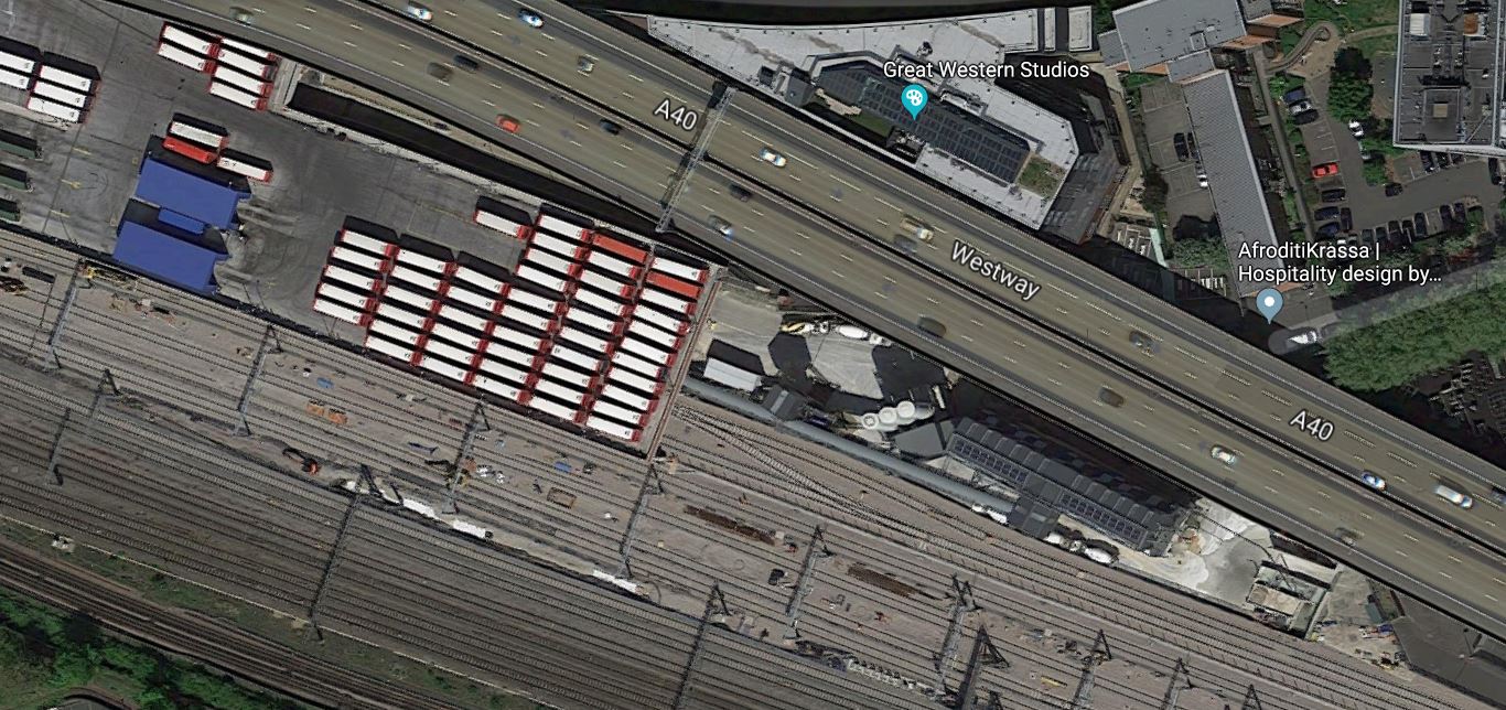
This Google Map shows Westbourne Park bus garage, nestled between the elevated M40 motorway and the rail lines out of Paddington station.
Note.
- All those white rectangles with red ends are buses.
- Running along the South side of the garage are the electrified Crossrail rail lines that go into the tunnel to Paddington and all points to the East.
- Below that are the electrified lines of the Great Western Main Line.
- The electrification gantries on both sets of lines are clearly visible.
There are also some lines which appear to go under the bus garage.
This Google Map shows those lines in more detail.
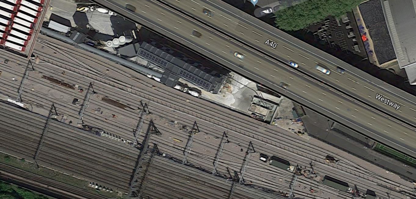
The new Westbourne Park Bus Garage was built so that Crossrail sidings for trains turning back at Paddington would be under the buses.
The image is dated 2018, but it clearly shows that the sidings don’t have electrification.
Could this be deliberate or does the image predate the installation of the overhead wires?
This Google Map is a few more metres close to the portal, where the trains enter the tunnel.
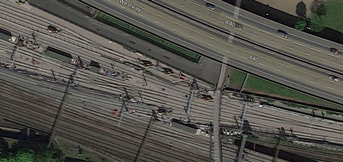
Note the footbridge going North-South over the area.
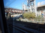
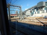
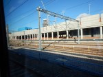
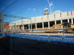
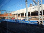
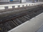
These pictures were taken from the footbridge of the tracks beneath the footbridge.
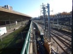


Looking at the pictures, the following can be ascertained.
- The bus garage is a concrete structure in the distance, highlighted by a topping of red buses.
- The sidings that go under the bus garage are not electrified.
- The Northernmost of the tracks, that go past the bus garage is not electrified. Perhaps, this track is used to allow diesel-hauled service trains to access the tunnel.
There would certainly be an advantage in not electrifying the sidings, as working in effectively the basement of a bus garage, if a fault developed with 25 KVAC all around you, would be a Health and Safety nightmare.
Passing The Bus Garage
Later I took a train past the bus garage and took these pictures.


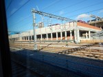
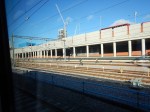


It is certainly, an impressive use of limited space.
Buses are lined up on the first floor of the garage.
I would suspect that the concrete plant will be dismantled, as this would allow more sidings to be laid out underneath the bus garage.
The Turnback
But did I get the answer to the question I posed?
From my observations on the bridge and after looking in detail at the Google Maps of the area, the turnback sidings are to the South of the bus garage. Note the intricate track layout in the third Google Map in this post.
The turnback also appears to be electrified.
Auto-Reverse
Perhaps the most interesting thing about the turnback, is contained in this article on Rail Engineer, which is entitled Signalling Crossrail. This is an extract.
A new facility called ‘auto reverse’ is being provided at Westbourne Park (no station) for turning the 14 trains per hour in the reversing sidings. The driver selects ‘auto reverse’ on leaving Paddington station and walks back through the train, obviating the need for drivers to ‘step-up’. By the time the train gets back to Paddington (about a mile) the driver should be in the other cab ready to form the next eastbound departure.
The facility has the capability to turn round a full 30 tph service. There is just time for the driver to walk back through the train whilst in the reversing siding but doing so on departure at Paddington gives that extra time that will also help recover from perturbation.
The article also says that Auto Reverse will not be provided on Network Rail infrastructure, but as these tracks between the bus garage and the Great Western Main Line are Crossral infrastructure, that would be irrelevant.
The Auto Reverse would appear to be a clever use of automation, which I suspect the driver can stop at any time using some form of remote control.
Is It Ready For Use?
I have to ask this question.
It looked to me, that there was still some work to do.
If Crossrail were to open in early December, then it looks that it could be impossible.
So were these works at Westbourne Park, the reason for the postponement?
Could Electric Trains Run On Long Scenic And Rural Routes?
In the UK we have some spectacular scenic rail routes and several long rural lines.
Basingstoke And Exeter
The West of England Main Line is an important rail route.
The section without electrification between Basingstoke and Exeter St. Davids stations has the following characteristics.
- It is just over one hundred and twenty miles long.
- There are thirteen intermediate stations, where the expresses call.
- The average distance between stations is around nine miles.
- The longest stretch between stations is the sixteen miles between Basingstoke and Andover stations.
- The average speed of trains on the line is around forty-four mph.
There is high quality 750 VDC third-rail electrification at the London end of the route.
Cumbrian Coast Line
The Cumbrian Coast Line encircles the Lake District on the West.
The section without electrification between Carnforth and Carlisle stations has the following characteristics.
- It is around a hundred and fourteen miles long.
- There are twenty-nine intermediate stations.
- The average distance between stations is around four miles.
- The longest stretch between stations is the thirteen miles between Millom and Silecroft stations.
- The average speed of trains on the line is around thirty-five mph.
There is also high standard 25 KVAC electrification at both ends of the line.
Far North Line
The Far North Line is one of the most iconic rail routes in the UK.
The line has the following characteristics.
- It is one-hundred-and-seventy-four miles long.
- There are twenty-three intermediate stations.
- The average distance between stations is around seven miles.
- The longest stretch between stations is the thirteen miles between Georgemas Junction and Wick stations.
- The average speed of trains on the line is around forty mph.
The line is without electrification and there is none nearby.
Glasgow To Oban
The West Highland Line is one of the most iconic rail routes in the UK.
The line is without electrification from Craigendoran Junction, which is two miles South of Helensburgh Upper station and the section to the North of the junction, has the following characteristics.
- It is seventy-eight miles long.
- There are ten intermediate stations.
- The average distance between stations is around eight miles.
- The longest stretch between stations is the twelve miles between Tyndrum Lower and Dalmally stations.
- The average speed of trains on the line is around thirty-three mph.
From Glasgow Queen Street to Craigendoran Junction is electrified with 25 KVAC overhead wires.
Glasgow To Mallaig
This is a second branch of the West Highland Line, which runs between Crianlarich and Mallaig stations.
- It is one hundred and five miles long.
- There are eighteen intermediate stations.
- The average distance between stations is around five miles.
- The longest stretch between stations is the twelve miles between Bridge Of Orchy and Rannoch stations.
- The average speed of trains on the line is around twenty-five mph.
Heart Of Wales Line
The Heart of Wales Line is one of the most iconic rail routes in the UK.
The line is without electrification and the section between Swansea and Shrewsbury stations, has the following characteristics.
- It is just over one hundred and twenty miles long.
- There are thirty-one intermediate stations.
- The average distance between stations is around four miles.
- The longest stretch between stations is the thirteen miles between Shrewsbury and Church Stretton stations.
- The average speed of trains on the line is just under forty mph.
There is also no electrification at either end of the line.
Settle And Carlisle
The Settle and Carlisle Line is one of the most iconic rail routes in the UK.
The section without electrification between Skipton and Carlisle stations has the following characteristics.
- It is just over eighty miles long.
- There are thirteen intermediate stations.
- The average distance between stations is around six miles.
- The longest stretch between stations is the sixteen miles between Gargrave and Hellifield stations.
- The average speed of trains on the line is around forty mph.
There is also high standard 25 KVAC electrification at both ends of the line.
Tyne Valley Line
The Tyne Valley Line is an important route between Carlisle and Newcastle stations.
The line is without electrification has the following characteristics.
- It is just over sixty miles long.
- There are ten intermediate stations.
- The average distance between stations is around six miles.
- The longest stretch between stations is the sixteen miles between Carlisle and Haltwhistle stations.
- The average speed of trains on the line is around mph.
There is also high standard 25 KVAC electrification at both ends of the line.
A Pattern Emerges
The routes seem to fit a pattern, with very similar characteristics.
Important Local Transport Links
All of these routes are probably important local transport links, that get children to school, many people to large towns for shopping and entertainment and passengers of all ages to see their friends and relatives.
Many would have been closed but for strong local opposition several decades ago.
Because of the overall rise in passengers in recent years, they are now relatively safe for a couple of decades.
Iconic Routes And Tourist Attractions
Several of these routes are some of the most iconic rail routes in the UK, Europe or even the world and are tourist attractions in their own right.
Some of these routes are also, very important in getting tourists to out-of-the-way-places.
Lots Of Stations Every Few Miles
The average distance between stations on all lines seems to be under ten miles in all cases.
This surprised me, but then all these lines were probably built over a hundred years ago to connect people to the expanding railway network.
The longest stretch between two stations appears to be sixteen miles.
Diesel Hauled
All trains seem to be powered by diesel.
This is surely very inappropriate considering that some of the routes go through some of our most peaceful and unspoilt countryside.
Inadequate Trains
Most services are run by trains, that are just too small.
I know to put a four-car train on, probably doubles the cost, but regularly as I explore these lines, I find that these two-car trains are crammed-full.
I once inadvertently took a two-car Class 150 train, that was on its way to Glastonbury for the Festival. There was no space for anything else and as I didn’t want to wait an hour for the next train, I just about got on.
Passengers need to be encouraged to take trains to rural events, rather than discouraged.
An Electric Train Service For Scenic And Rural Routes
What would be the characteristics of the ideal train for these routes?
A Four-Car Electric Train
Without doubt, the trains need to be four-car electric trains with the British Rail standard length of around eighty metres.
Dual Voltage
To broaden the applications, the trains should obviously be capable of running on both 25 KVAC overhead and 750 VDC third-rail electrification.
100 mph Capability
The trains should have at least a 100 mph capability, so they can run on main lines and not hold up other traffic.
No Large Scale Electrification
Unless there is another reason, like a freight terminal, quarry, mine or port, that needs the electrification, using these trains must be possible without any large scale electrification.
Battery, Diesel Or Hydrogen Power
Obviously, some form of power will be needed to power the trains.
Diesel is an obvious no-no but possibly could only be used in a small way as emergency power to get the trains to the next station, if the main power source failed.
I have not seen any calculations about the weight, size and power of hydrogen powered trains, although there have been some professional videos.
But what worries me about a hydrogen-powered train is that it still needs some sizeable batteries.
So do calculations indicate that a hydrogen-powered train is both a realisable train and that it can be produced at an acceptable cost?
Who knows? Until, I see the maths published in a respected publication, I will reserve my judgement.
Do Bombardier know anything?
In the July 2018 Edition of Modern Railways, there is an article entitled Bi-Mode Aventra Details Revealed.
A lot of the article takes the form of reporting an interview with Des McKeon, who is Bombardier’s Commercial Director and Global Head of Regional and Intercity.
This is a paragraph.
However, Mr McKeon said his view was that diesel engines ‘will be required for many years’ as other power sources do not yet have the required power or efficiency to support inter-city operation at high-speeds.
As Bombardier have recently launched the Talent 3 train with batteries that I wrote about in Bombardier Introduces Talent 3 Battery-Operated Train, I would suspect that if anybody knows the merits of hydrogen and battery power, it is Mr. McKeon.
So it looks like we’re left with battery power.
What could be a problem is that looking at all the example routes is that there is a need to be able to do station-to-station legs upwards of thirteen-sixteen miles.
So I will say that the train must be able to do twenty miles on battery power.
How Much Battery Capacity Should Be Provided On Each Train?
In Issue 864 of Rail Magazine, there is an article entitled Scotland High Among Vivarail’s Targets for Class 230 D-Trains, where this is said.
Vivarail’s two-car battery units contains four 100 kWh lithium-ion battery rafts, each weighing 1.2 tonnes.
If 200 kWh can be placed under the floor of each car of a rebuilt London Underground D78 Stock, then I think it is reasonable that up to 200 kWh can be placed under the floor of each car of the proposed train.
As it would be required that the train didn’t regularly run out of electricity, then I wouldn’t be surprised to see upwards of 800 kWh of battery installed in the train.
n an article in the October 2017 Edition of Modern Railways, which is entitled Celling England By The Pound, Ian Walmsley says this in relation to trains running on the Uckfield Branch, which is not very challenging.
A modern EMU needs between 3 and 5 kWh per vehicle mile for this sort of service.
So if we are aiming for a twenty mile range from a four-car train with an 800 kWh battery, this means that any energy consumption better than 10 kWh will achieve the required range.
Regular Charging At Each Station Stop
In the previous section, I showed that the proposed train with a full battery could handle a twenty mile leg between stations.
But surely, this means that at every stop, the electricity used on the previous leg must be replenished.
In Porterbrook Makes Case For Battery/Electric Bi-Mode Conversion, I calculated the kinetic energy of a four-car Class 350 train, with a full load of passengers, travelling at ninety mph, as 47.1 kWh.
So if the train is travelling at a line speed of ninety mph and it is fitted with regenerative braking with an efficiency of eighty percent, 9.4 kWh of energy will be needed for the train to regain line speed.
There will also be an energy consumption of between 3 kWh and 5 kWh per vehicle per mile.
For the proposed four-car train on a twenty mile trip, this will be between 240 and 400 kWh.
This will mean that between 240 and 400 kWh will need to be transferred to the train during a station stop, which will take one minute at most.
I covered en-route charging fully in Charging Battery/Electric Trains En-Route.
I came to this conclusion.
I believe it is possible to design a charging system using proven third-rail technology and batteries or supercapacitors to transfer at least 200 kWh into a train’s batteries at each stop.
This means that a substantial top up can be given to the train’s batteries at stations equipped with a fast charging system.
New Or Refurbished Trains?
New trains designed to meet the specification, could obviously be used.
But there are a several fleets of modern trains, which are due to be replaced. These trains will be looking for new homes and could be updated to the required battery/electric specification.
- Greater Anglia – 30 x Class 379 trains.
- Greater Anglia – 26 x Class 360 trains.
- London North Western Railway – 77 x Class 350 trains.
- TransPennine Express – 10 x Class 350 trains
In Porterbrook Makes Case For Battery/Electric Bi-Mode Conversion, I describe Porterbrook’s plans to convert a number of Class 350 trains to battery/electric trains.
These Class 350 Battery/FLEX trains should meet the specification needed to serve the scenic and rural routes.
Conclusion
I am led to the conclusion, that it will be possible to design a battery/electric train and charging system, that could introduce electric trains to scenic and rural routes all over the UK, with the exception of Northern Ireland.
But even on the island of Ireland, for use both North and South of the border, new trains could be designed and built, that would work on similar principles.
I should also say, that Porterbrook with their Class 350 Battery/FLEX train seem to have specfied a train that is needed. Pair it with the right charging system and there will be few no-go areas in mainland UK.
Charging Battery/Electric Trains En-Route
One big need with a battery/electric hybrid train, is the need to charge the batteries quickly at a station stop.
On my last trip to Sheffield, I timed the stops from brakes on to moving again of the Class 222 train.
Times in minutes:seconds were as follows.
- Leicester 1:30
- Louthborough 1:15
- East Midlands Parkway 1:06
- Long Eaton 1:08
- Derby 1:22
- Chesterfield 1:09
So it looks like there is only a minute to charge the batteries on a typical Inter-City service.
Would it be much longer on say a long rural service like Settle and Carlisle or Inverness to Wick?
I don’t think so!
So how could we top up the train in a station stop of less than a minute.
Plug The Train Into a Power Socket
This may work with electric cars, but if you think it would work with trains and charge them in a minute, then think again!
Using A Pantograph
This may seem to be the obvious way, but to raise the pantograph, get a reasonable charge into the train’s batteries and lower it again, is an awful lot of things to cram into a minute.
There’s also many things that can go wrong.
Vivarail’s Solution
In Issue 864 of Rail Magazine, there is an article entitled Scotland High Among Vivarail’s Targets for Class 230 D-Trains, Vivarail’s solution to charging a battery-powered Class 230 train is disclosed.
A prototype rapid charging facility at its Long Marston base would use short sections of third-rail to quickly recharge a Class 230’s batteries. He said that the third-rail shoegear fitted to the trains in their London Underground service could handle higher currents than simply plugging a cable into the train.
The rapid charging concept consists of a shipping container of batteries that are trickle charged from a mains supply. When a Class 230 sits over the short sections of third-rail, electricity can be quickly transferred to the train’s batteries. When the train is away, the power rails are earthed to ensure they pose no risk The concept provides for charging a Class 230 as it pauses at a terminus before making its return journey.
What surprises me, is the claim, that third-rail is such an effective way of charging the batteries.
But then a Class 92 locomotive has a power of 4,000 kW when running on 750 VDC third rail electrification, so it would appear third-rail systems can handle large amounts of power.
This would be the sequence, as a train performed a station stop.
- The driver would stop the train at the defined place in the platform, as thousands of train drivers do all over the world, millions of times every day.
- Once stopped, the contact shoes on the train would be in contact with the third rail, as they would be permanently down and ready to accept electricity at all times.
- The charging system would detect the stationary train and that the train was connected, and switch on the power supply. to the third-rail.
- Electricity would flow from the track to the batteries, just as if the train was on a standard third-rail electrified track.
- If the train’s battery should become full, the train’s system could stop the charging.
- When passengers had finished leaving and joining the train and it was safe to do so, the driver would start the train and drive it to the next station, after ascertaining, that there was enough power in the batteries.
- When the charging system determined that the train was moving or that the contact shoe was no longer connected to the third-rail, it would immediately cut the power to the rail and connect it to earth.
It is a brilliant system; simple, efficient and fail-safe.
- Regenerative braking will mean that stopping in the station will help to top-up the batteries.
- The battery on the train is being charged, as long as it is stationary in the station.
- Delays in the station have no effect on the charging, except to allow it for longer if the battery can accept more charge.
- The driver concentrates on driving the train and doesn’t have to do anything to start and stop the charging.
- As there is no cable to disconnect or pantograph to lower, disconnection from the charging system is automatic and absolute, when the train leaves.
- The charging system never exposes a live rail to passengers and staff.
As a Control and Electrical Engineer, I believe that developments of this system, could be able to put at least 200 kWh into the train’s batteries at each stop.
The system could also be independent of the driver, whose only actions would be to check on safety, that charging was proceeding as it should and that there was sufficient charge in the batteries before continuing.
Connection And Disconnection To The Third-Rail
These pictures taken at Blackfriars station, show how the ends of the third-rail is tapered, so that the shoe on the train connects and disconnects smoothly.
Note.
- The tapered ends of both rails on opposite side of the gaps.
- For safety, the electrified third-rail is on the other side of the track to the platform.
- One picture shows how yellow-painted wood is used for extra safety.
As a train is always on top of the third-rail, when the power to the rail is switched on in Vivarail’s charging system, I think that, the system should be very safe.
Battery-To-Battery Energy Transfer
Vivarail’s genius is to transfer the energy from trackside batteries to the batteries on the train. As batteries have a low impedance, large amounts of electricity can be passed quickly.
Batteries, Supercapacitors Or Both?
I believe that in a few years time for many applications, supercapacitors will be a viable alternative to batteries.
Energy densities are improving in supercapacitors and they have a similar low impedance, which will enable fast transfer of electricity.
So I wouldn’t be surprised to supercapacitors used on trains or in charging systems.
It may be that a mix of supercapacitors and batteries is the optimal solution.
Installing A Vivarail-Style Charging System
Installation of a Vivarail-style charging system would require.
- A length of third rail to be installed alongside the track or tracks in the station.
- The containerised batteries and control system to be installed in a suitable place.
- Electrical power to be connected to the batteries and control system.
- Appropriate-cabling between the rail and the container.
The great advantage is that to install a charging system in a station would not require any of the complicated and expensive works, often needed to install 25 KVAC overhead electrification.
Supplying Electricity To A Vivarail-Style Charging System
The Rail Magazine article talks of trickle charging the track-side batteries, using mains electricity, but I suspect some of the most cost-effective systems would use solar, wind or water power, backed up by a mains supply.
In a remote station, installing a Vivarail-style charging system powered by a sustainable power might be an opportunity to install modern low-energy lights and other equipment at the station, powered from the charging system.
A Vivarail-Style Charging System Could Be Built With No Visual Intrusion
Another advantage of using Vivarail-style charging systems, is that there is less visual intrusion than traditional continuous 25 KVAC overhead electrification.
Some visual intrusion would be down to the shipping container used to house the batteries.
But if necessary, the batteries could be housed in a classic Victorian outhouse or a modern sympathetically-designed structure.
Would A Vivarail-Style Charging System Need To Be In A Station?
Many, but not all charging systems would be in stations.
However, there are some very convenient places for charging systems, that may not be in stations.
Trains going to Bedwyn station wait for several minutes in a turnback siding to the West of the station, before returning to London. The route is not electrified and bi-mode Class 800 trains will be used on the route, because there is about thirteen miles between Bedwyn and Newbury without electrification.
If a Vivarail-style charging system were to be added to the turnback siding battery/electric trains could work the service to London. I’m sure Hitachi know how to convert a version of a Class 80x train to battery/electric operation.
There will be quite a few places, where for operational reasons, a charging system could or should be placed.
Would All Stations On A Route Need To Be fitted With A Vivarail-Style Charging System?
This would depend on the route and the need to run it reliably.
Detailed computer modelling would show, which stations wouldn’t need to be fitted with charging systems!
If a train was a limited-stop service or not required to stop at a particular station because of operational reasons or the timetable, the train would just pass through the station.
As it didn’t stop, it would not have caused the charging system to switch on power to the third-rail.
But if say due to delays caused by an incident meant a train was low on battery power, there is no reason, why the train can’t make a stop at any charging system to top-up the batteries.
Should The Driver Have Any Control?
Consider.
- It may be extra safety is needed, so the driver could give a signal to the charging system, that it is safe to start the charging process.
- Similarly, the driver should be able to pause or stop the process at any time.
But the driver would mainly be monitoring an automatic process.
Would The Charging System Be Linked To The Signalling?
I think this could be likely, as this could add another level of safety.
Conclusion
I believe it is possible to design a safe charging system using proven third-rail technology and batteries or supercapacitors to transfer at least 200 kWh into a train’s batteries at each stop.
Surely, this method of electrification could be used to allow electric trains to run through environmentally-sensitive areas and World Heritage sites like Bath, the Lake District and the Forth Bridge,
Could A 125 Mph Electric Train With Batteries Handle The Midland Main Line?
In Bombardier’s 125 Mph Electric Train With Batteries, I investigated a pure electric train based on Bombardier’s proposed 125 mph bi-mode Aventra with batteries.
It would have the following characteristics.
- Electric power on both 25 KVAC overhead and 750 VDC third-rail.
- Appropriately-sized batteries.
- 125 mph running, where possible on electrification and/or battery power.
- Regenerative braking using the batteries.
- Low energy interiors and systems.
It would be a train with efficiency levels higher than any train seen before.
It would also be zero-carbon at the point of delivery.
An Example 125 mph Train
I will use the same size and specification of train, that I used in Bombardier’s 125 Mph Electric Train With Batteries.
- The train is five cars, with say four motored cars.
- The empty train weighs close to 180 tonnes.
- There are 430 passengers, with an average weight of 90 Kg each, with baggage, bikes and buggies.
- This gives a total train weight of 218.7 tonnes.
- The train is travelling at 200 kph or 125 mph.
Travelling at 200 kph, the train has an energy of 94.9 kWh.
I will also assume.
- The train uses 15 kWh per mile to maintain the required line speed and power the train’s systems.
- Regenerative braking is eighty percent efficient.
I will now do a few calculations.
Kettering To Leicester
Suppose one of the proposed trains was running between St. Pancras and Leicester.
- I’m assuming there are no stops.
- In a year or two, it should be able to run as far as Kettering using the new and improved 25 KVAC overhead electrification.
- The train would leave the electrification at Kettering with a full charge in the batteries.
- The train would also pass Kettering as close to the line speed as possible.
- Hopefully, the twenty-nine miles without electrification between Kettering and Leicester will have been updated to have the highest possible line speed, with many sections capable of supporting 125 mph running.
I can do a rough-and-ready calculation, as to how much energy has been expended between Kettering and Leicester.
- Twenty-nine miles at 15 kWh per mile is 435 kWh.
- The train has a kinetic energy of 94.9 kWh at 125 mph and twenty percent will be lost in stopping at Leicester, which is 19 kWh.
This means that a battery of at least 454 kWh will be needed to propel the train to Leicester.
Kettering To Sheffield
If the train went all the way without stopping between Kettering and Sheffield, the energy used would be much higher.
One hundred-and-one miles at 15 kWh is 1515 kWh.
So given that the train will be slowing and accelerating, we’re probably talking of a battery capacity of around 2000 kWh.
In our five-car example train, this is 400 kWh per car.
Kettering To Sheffield With Stops
The previous calculation shows what can be achieved, but we need a practical train service.
When I last went to Sheffield, the train stopped at Leicester, Loughborough, East Midlands Parkway, Long Eaton, Derby and Chesterfield.
I have built an Excel spreadsheet, that models this route and it shows that if the train has a battery capacity of 2,000 kWh, the train will get to Sheffield with 371 kWh left in the battery.
- Increase the efficiency of the regenerative braking and the energy left is 425 kWh.
- Reduce the train’s energy consumption to 12 kWh per mile and the energy left is 674 kWh.
- Do both and the energy left is 728 kWh.
The message is clear; train manufacturers and their suppliers should use all efforts to improve the efficiencies of trains and all of their components.
- Aerodynamics
- \Weight savings
- Bogie dynamics
- Traction motors
- Battery capacity and energy density
- Low energy lighting and air-conditioning
No idea however wacky should be discarded.
Network Rail also has a part to play.
- The track should have as a high a line speed as is practical.
- Signalling and timetabling should be designed to minimise interactions with other services.
Adding all these together, I believe that in a few years, we could see a train, that will consume 10 kWh per mile and have a regenerative braking efficiency of ninety-five percent.
If this can be achieved then the train will have 960 kWh in the batteries when it arrives in Sheffield.
Sheffield To Kettering
There is no helpful stretch of electrification at the Sheffield end of the route, so I will assume that there is a method of charging the batteries at Sheffield.
Unsurprisingly, as the train is running the same total distance and making the same number of stops, if the train starts with a full battery at Sheffield, it arrives at Kettering with the same amount of energy in the battery, as on the Northbound-run to Sheffield.
An Interim Conclusion
I am led to the interim conclusion, that given the continued upward curve of technology and engineering, that it will be possible to run 125 mph electric trains with an appropriately-sized battery.
How Much Battery Capacity Can Be Installed In A Train?
In Issue 864 of Rail Magazine, there is an article entitled Scotland High Among Vivarail’s Targets for Class 230 D-Trains, where this is said.
Vivarail’s two-car battery units contains four 100 kWh lithium-ion battery rafts, each weighing 1.2 tonnes.
Consider.
- Vivarail’s cars are 18.37 metres long.
- Car length in a typical Aventra, like a Class 720 train, is 24 metres.
- Aventras have been designed for batteries and supercapacitors, whereas the D78 trains, used as a base for the Class 230 train,were not.
- Batteries and supercapacitors are getting better all the time.
- Batteries and supercapacitors can probably be built to fit in unusually-shaped spaces.
I wouldn’t be surprised to see Aventras being able to take double the capacity of a Class 230 train under each car.
I wouldn’t rule out 2,000 kWh energy storage capacity on a five-car train, that was designed for batteries.
The actual size installed would depend on operator, weight, performance and cost.
My Excel spreadsheet shows that for reliable operation between Kettering and Sheffield, a battery of at least 1200 kWh is needed, with a very efficient train.
Charging Trains En-Route
I covered en-route charging fully in Charging Battery/Electric Trains En-Route.
I came to this conclusion.
I believe it is possible to design a charging system using proven third-rail technology and batteries or supercapacitors to transfer at least 200 kWh into a train’s batteries at each stop.
This means that a substantial top up can be given to the train’s batteries at stations equipped with a fast charging system.
An Astonishing Set Of Results
I use astonishing lightly, but I am very surprised.
I assumed the following.
- The train uses 15 kWh per mile to maintain the required line speed and power the train’s systems.
- Regenerative braking is eighty percent efficient.
- The train is fitted with 600 kWh of energy storage.
- At each of the six stations up to 200 kWh of energy can be transferred to the train.
Going North the train arrives in Sheffield with 171 kWh in the energy storage.
Going South the train arrives at Kettering with 61 kWh in the energy storage.
Probably a bit tight for safety, but surprising nevertheless.
I then tried with the following.
- The train uses 12 kWh per mile to maintain the required line speed and power the train’s systems.
- Regenerative braking is ninety percent efficient.
- The train is fitted with 500 kWh of energy storage.
- At each of the six stations up to 200 kWh of energy can be transferred to the train.
Going North the train arrives in Sheffield with 258 kWh in the energy storage.
Going South the train arrives at Kettering with 114 kWh in the energy storage.
It would appear that increasing the efficiency of the train gives a lot of the improvement.
Finally, I put everything, at what I feel are the most efficient settings.
- The train uses 10 kWh per mile to maintain the required line speed and power the train’s systems.
- Regenerative braking is ninety-five percent efficient.
- The train is fitted with 500 kWh of energy storage.
- At each of the six stations up to 200 kWh of energy can be transferred to the train.
Going North the train arrives in Sheffield with 325 kWh in the energy storage.
Going South the train arrives at Kettering with 210 kWh in the energy storage.
These sets of figures prove to me, that it is possible to design a 125 mph battery/electric hybrid train and a set of charging stations, that will make St. Pancras to Sheffield by electric train, a viable possibility without any more electrification.
Should The Train Be Fitted With A Means Of Charging The Batteries?
Why not?
Wires do go down and rest assured, a couple of battery/electric hybrids would get stuck!
So a small diesel or hydrogen generator to allow a train to limp a few miles might not be a bad idea.
Electrification Between Sheffield And Clay Cross On The Midland Main Line
In The UK’s New High Speed Line Being Built By Stealth, there is a sub-section with the same title as this sub-section.
This is the first part of that sub-section.
This article on Rail Technology Magazine is entitled Grayling Asks HS2 To Prepare For Electrification Of 25km Midland Main Line Route.
If this electrification happens on the Midland Main Line between Sheffield and Clay Cross, it will be another project in turning the line into a high speed route with a 200 kph operating speed, between London and Sheffield.
Currently, the electrified section of the line South of Bedford is being upgraded and the electrification and quadruple tracks are being extended to Glendon Junction, where the branch to Corby leaves the main line.
The proposed electrification will probably involve the following.
- Upgrading the line to a higher speed of perhaps 225 kph, with provision to increase the speed of the line further.
- Rebuilding of Chesterfield station in readiness for High Speed Two.
- Full electrification between Sheffield and Clay Cross.
Clay Cross is significant, as it is where the Midland Main Line splits into two Southbound routes.
- The main route through the Derwent Valley Mills World Heritage Site and Derby station.
- The secondary route of the Erewash Valley Line to the East Midlands Hub station.
Note.
- Some of the tunnel portals in the Derwent Valley are Listed.
- Trying to electrify the line through the World Heritage Site will be a legal and engineering nightmare.
- Network Rail has spent or is spending £250million on upgrading the Erewash Valley Line.
- High Speed Two will reach The East Midlands Hub station in 2032.
When High Speed Two, is extended North from the East Midlands Hub station, it will take a route roughly following the M1. A spur will link High Speed Two to the Erewash Valley line in the Clay Cross area, to enable services to Chesterfield and Sheffield.
But until High Speed Two is built North of the East Midlands Hub station, the Erewash Valley Line looks from my helicopter to be capable of supporting 200 kph services.
If this electrification is performed, it will transform the prospects for battery/electric hybrid trains between London and Sheffield.
- Trains will have to run fifteen miles less on battery power.
- Trains will arrive in both St. Pancras and Sheffield with batteries that are at least three-quarters full.
- Returning the trains will fill them up on the electrification at the end of the line.
- There will probably not be a need for charging systems at St. Pancras, Chesterfield and Sheffield.
I also think, that as the train could arrive in Sheffield with a full battery, there is the possibility of extending services past Sheffield to Barnsley, Huddersfield and cLeeds, if the operator felt it was a worthwhile service.
Nottingham
Nottingham is just eight miles from East Midlands Parkway station, which is less distance than Derby.
So if the battery/electric hybrid trains can reach Derby from Kettering on Battery power, with some help from charging at Leicester and Loughborough, the trains can reach Nottingham, where charging would be installed.
Conclusion
From my calculations, I’m sure that an efficient battery/electric hybrid train can handle all current services on the Midland Main Line, with third-rail charging at intermediate stations.
I do think though, that if Sheffield to Clay Cross Junction is electrified in preparation for High Speed Two, that it makes the design easier and the economics a lot better.
It would also give Sheffield a genuine sub-two hour service to London, which would only get better.
Station Dwell Times On The London Overground
This afternoon, I had to go to Walthamstow for lunch, so on the way out, I checked how long it was between brakes on at James Street station and the Class 315 train was moving again.
The dwell time was a very respectable thirty seconds, which is probably more down to the driver and the signalling, than the nearly-forty-year-old train.
Coming back, I took the Gospel Oak to Barking Line to Gospel Oak station..
The driver gave a display of precision driving a Class 172 train, with the intermediate stops, all taking thirty seconds or less.
From Gospel Oak, I switched to the North London Line and took a Class 378 train to Canonbury station, from where I walked home.
The dwell times on this line were more variable, with two times at thirty seconds or less, two at nearly two minutes and the rest in-between.
From these small number of observations, it would appear that the minimum dwell time on the London Overground is thirty seconds.
Various factors will determine the actual dwell time.
- Trains must not leave early, as passengers don’t like this.
- Trains must not leave, before the driver has ascertained it is safe to do so.
- If a train arrives early, then the dwell time might be lengthened, even if the train leaves on time.
- Large numbers of passengers or a passenger in a wheelchair, who needs a ramp will lengthen the dwell time.
I should say that today, the trains were not full and there were plenty of empty seats.
Conclusions
If trains and drivers can handle thirty second dwell times, then everything else associated with a station stop, must be capable of the same fast response.
This thirty-second dwell time may have repercussions for rapid charging of battery/electric trains, that I wrote about in Charging A Battery-Powered Class 230 Train.
I think there are three options for charging a train at a station stop.
Plug the Train Into A Power Socket
Can you plug you mobile phone into the mains, give it a reasonable charge and then disconnect it and store all leads in thirty seconds?
Use a Pantograph To Connect To 25 KVAC Overhead Electrification
Even if a driver or automation is very fast at raising and lowering the pantograph, I don’t believe that in a total time of thirty seconds, enough electricity can be passed to the train.
This method might work well in longer stop at a terminal station, but it is unlikely, it could be used successfully at an intermediate stop.
Use 750 VDC Third-Rail Electrification
750 VDC third-rail electrification has a very big advantage, in that, trains can connect and disconnect to the electrification automatically, without any driver intervention.
Look at this picture of a train going over a level-crossing.

The ends of the third-rails on either side or the crossing are sloped so that the contact shoes on the train can disconnect and connect smoothly.
As you have to design the system for a possible thirty-second stop and don’t have the time available for the first two options, I am fairly certain, that the only way a worthwhile amount of electricity can be transferred to the train’s battery, is to use some form of system based on tried-and-tested 750 VDC third rail electrification.
There may also be advantages in using a longer length of third-rail, so that the connection time is increased and more than one contact shoe can connect at the same time.
Automation would control the power to the third-rail, so that no live rail is exposed to passengers and staff.
After all a train on top, is a pretty comprehensive safety guard.
.
Could A Class 450 Battery/FLEX Train Be Used Between Waterloo And Exeter?
When I wrote Porterbrook Makes Case For Battery/Electric Bi-Mode Conversion, Issue 864 of Rail Magazine hadn’t been published. The magazine contained details of Vivarail’s proposed rapid charging facility, which I wrote about in Charging A Battery-Powered Class 230 Train.
Consequently, at the time, I came to the conclusion that a Class 450 train with a Battery/FLEX conversion, similar to Porterbrook’s one for a Class 350 train, couldn’t stretch between Waterloo and Exeter, as it was just too far.
But Vivarail’s proposed rapid charging facility could change everything!
The West of England Main Line is electrified as far as Basingstoke station, from where the route is worked excursively by diesel Class 159 trains.
Between Basingstoke and Exeter St. Davids stations, the trains make fourteen stops.
- Most station stops,take up to a minute, but could take longer if say the train is busy or there’s a passenger in a wheelchair.
- The train stops at Salisbury for four minutes, possibly to allow loading and unloading of catering trolleys.
- The distances between stations range between a few and eighteen miles.
- In Porterbrook Makes Case For Battery/Electric Bi-Mode Conversion, I said that if a 400 kWh battery were to be fitted to a Class 350/2 train, that this would give a range between twenty and fifty miles.
- The Class 350 and South Western Railway’s Class 450 trains are the same basic Siemens Desiro train, although the Class 350 train uses 25 KVAC overhead electrification and the Class 450 train uses 750 VDC third-rail electrification.
It would appear that if the train could be charged at each station, it should be able to hop all the way between Basingstoke and Exeter St. Davids stations.
Using a traditional charger, where the train would have to be physically plugged into the charger, wouldn’t be possible in the short station stops on the route.
Even raising a pantograph to connect to a 25 KVAC overhead line would be slow and could distract the driver, whilst they were doing more important things.
But Vivarail’s proposed rapid charging facility, which I am sure is automatic would give the battery a top-up without any driver intervention.
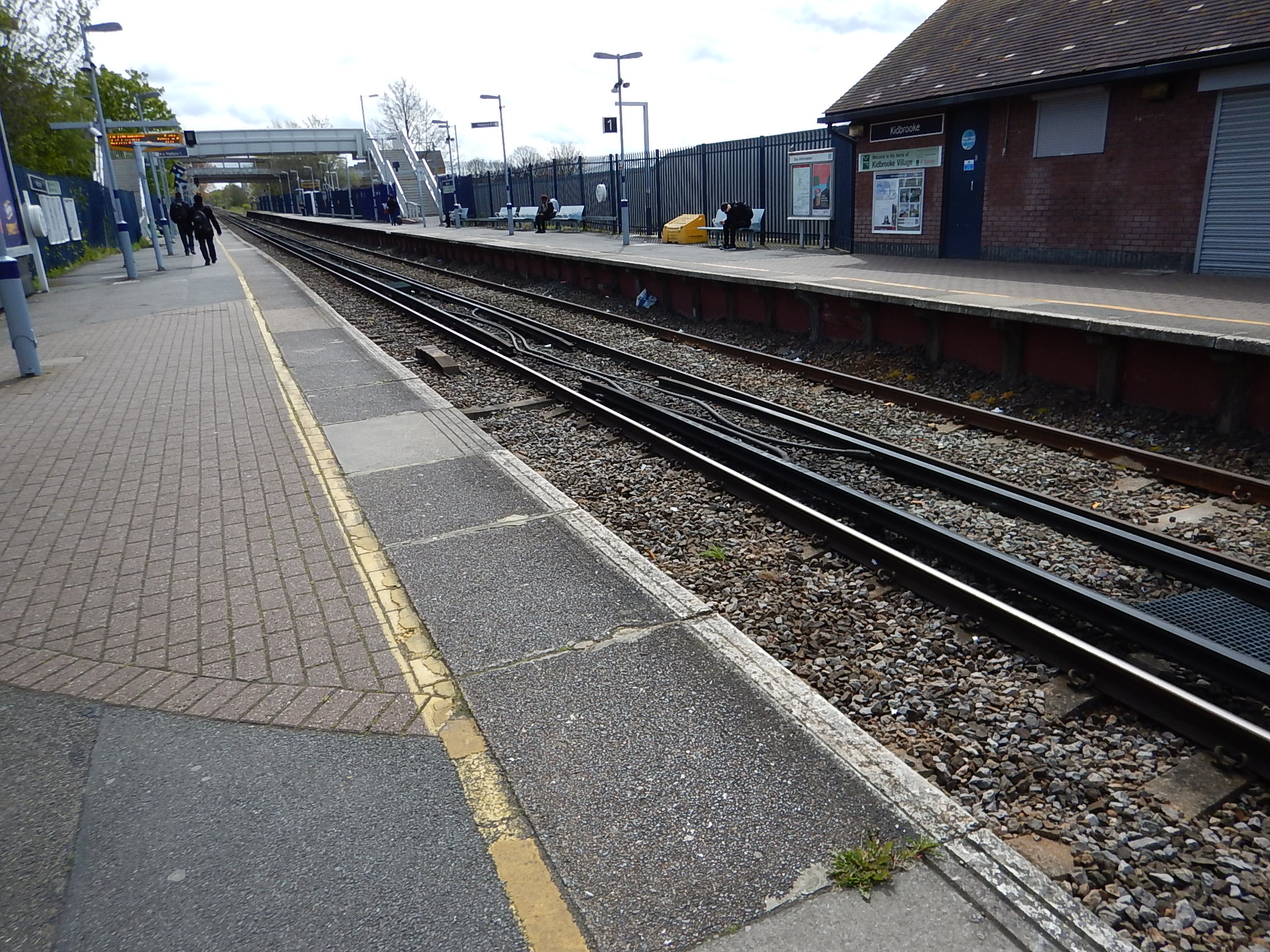
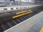
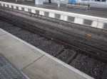
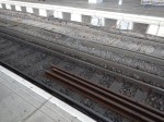
The charging system would have a third rail on the opposite side of the track to the platform, as in this picture of Kidbrooke station.
The third-rail would be.
- Short enough to be shielded by a train stopping on top.
- Long enough to connect to at least two contact shoes on the train.
- Automatically earthed, when no train is present and connected.
This would be the sequence, as a train stopped in a station.
- The driver would stop the train at the defined place in the platform, as thousands of train drivers do all over the world, millions of times every day.
- Once stopped, the contact shoes on the train would be in contact with the third rail, as they would be permanently down, as they are when running on third-rail electrification.
- The charging system would detect the stationary train and that the train was connected, and switch on the power supply. to the third-rail.
- Electricity would flow from the track to the batteries, just as if the train was on a standard third-rail electrified track.
- If the battery should become full, the train’s system could stop the charging.
- When passengers had finished leaving and joining the train and it was safe to do so, the driver would start the train and drive it to the next station.
- When the charging system determined that the train was moving or that the contact shoe was no longer connected to the third-rail, it would immediately cut the power to the rail and connect it to earth.
It is a brilliant system; simple, efficient and fail-safe.
- Regenerative braking will mean that stopping in the station will help to top-up the batteries.
- The battery on the train is being charged, as long as it is stationary in the station.
- Delays in the station have no effect on the charging, except to allow it for longer if the battery can accept more charge.
- The driver concentrates on driving the train and doesn’t have to do anything to start and stop the charging.
- The charging system never exposes a live rail to passengers and staff.
The charging system may also help recovery after an incident.
Suppose a fallen tree or a herd of cows has blocked the line and the electricity used to power the train’s systems has used a lot of battery power, so that when the train eventually gets to the next station, the battery needs a long charge before continuing.
The driver would just wait in the station, charging the battery, until there is enough energy to safely proceed.
A Look At The Mathematics
I shall now look at the mathematics of a leg between Basingstoke and Andover stations.
I will assume the following.
- The train will leave the electrification at Basingstoke with a full battery, containing 400 kWh of electricity, as it will have been charged on the way from Waterloo.
- The train is running at an operating speed of up to 90 mph between stations where possible, which means it has a kinetic energy of 47.1 kWh.
- For each mile, the train consumes 8 kWh of electricity, to power the trains services and maintain the required speed.
- Regenerative braking is eighty percent efficient.
As Basingstoke to Andover is eighteen miles, this means that energy consumption in the leg and the stop at Andover is as follows.
- 144 kWh is used to power the train and maintain speed.
- 9.42 kWh is lost in the braking and acceleration back to operating speed..
So the train will lose about 154 kWh on the eighteen mile leg.
I have built an Excel spreadsheet of the route and it looks that if a minimum of 100 kWh can be transferred to the train’s battery at each stop and the train uses no more than 8 kWh per mile, that it should be possible for the train to go from Basingstoke to Exeter on battery power.
Obviously, there are ways to make this journey more certain.
- Reduce the train’s energy consumption for items like lighting and air-conditioning..
- Improve the efficiency of regenerative braking.
- Improve the charging systems, so more electricity is transferred in the short stops.
- Improve the track, so that it is as smooth as possible with gentle curves.
- Fit a larger battery.
It requires different teams of engineers to optimise their own area, so all contribute to a more energy-efficient system.
Would Battery Power Work If The Line Speed Was Increased to 100 mph?
I have done this calculation assuming an operating speed of 100 mph, rather than the current 90 mph determined in part by the maximum speed of the Class 159 trains and it appears to be still possible.
Could 100 kWh Be Transferred To The Train In The Short Stops?
In Station Dwell Times On The London Overground, I showed that the London Overground regularly has station stops of under thirty seconds.
Even to me, as an trained Electrical Engineer, 100 kWh does seem a lot of power to transfer to the train in a stop that is that short.
In the related post, I postulated that a thirty-second dwell time, means that the only way to connect the train to the rapid charging system is to use third-rail electrification, as this connects and disconnects automatically.
This was said about Vivarail’s charging system in Issue 864 of Rail Magazine.
The rapid charging concept consists of a shipping container of batteries that are trickle charged from a mains supply. When a Class 230 sits over the short sections of third-rail, electricity can be quickly transferred to the train’s batteries. When the train is away, the power rails are earthed to ensure they pose no risk The concept provides for charging a Class 230 as it pauses at a terminus before making its return journey.
The key is the battery-to-battery transfer of electricity, as batteries have a low impedance and are designed to supply high electrical currents for a short time, as when starting a massive diesel engine in a truck.
This page shows a 12v 250Ah battery available for just over three hundred pounds.
- This battery alone has a capacity of 3 kWh.
- It is 518mm x 273mm x 240mm.
- It weighs 61 Kg.
You’d get a lot of these in a twenty-foot shipping container, which according to Wikipedia has a volume of 33.2 m³.
I estimate that a hundred of these batteries would fit easily into the container with all their control gear and electronics, which would mean a total capacity of 300 kWh.
Running my Excel spreadsheet with a 200 kWh transfer at each station, shows that the train can leave many stations with a full battery.
I have also run a more difficult scenario.
- For each mile, the train consumes 10 kWh of electricity instead of 8 kWh, to power the trains services and maintain the required speed.
- The rapid charging system can only transfer 80 kWh in thirty seconds.
The train still appears to get to its destination.
Obviously, Porterbrook, Siemens and Vivarail have better data than I have and will know what the actual performance of their trains and systems are.
How Much Power Can The Third-Rail Handle?
It should also be noted that a Class 450 train has eight x 250 kW traction motors, so the third-rail system of the train, must be capable of handling all of these at full power, when running on lines with third-rail electrification.
Would One Charging System Handle Both Tracks?
The route is double-track, with often platforms on either side of the tracs.
This Google Map shows Gillingham station, which appears to have a typical layout.
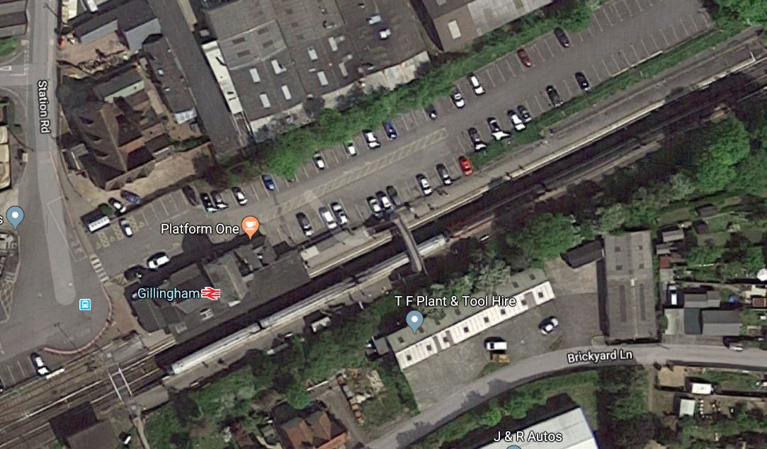
Note the three-car Class 159 train in the station.
If both tracks were to have a charging rail, I can’t see why one set of batteries shouldn’t be able to feed both tracks with separate control systems.
Although it does appear that several stations often use the same platforms for both directions.
Conclusion
This could be a very affordable way of electrifying a line with a lot of stations.
The Paddington Fiasco
Everybody is looking for a scapegoat for the problems at Paddington station, that is reported in this article on the BBC, which is entitled Paddington Station: Passengers Face Major Disruption.
Tony Miles of Modern Railways was on BBC Breakfast this morning and he explained what happened.
The Class 802 train was accumulating the 2,000 miles it needs before it can be accepted by Great Western Railway.
The trains are designed to be able to change from diesel to electric power and vice-versa at line speed.
This train was raising the pantograph to access the pverhead wires on a section of British Rail-era overhead wires at Ealing.
The pantograph is thought to have bounced and the overhead wires have broken and become entangled in the pantograph.
Modern electrification with its heavyweight gantries has each line wired separately, but according to Tony Miles, the British Rail lightweight system, means if one comes down, they all fail.
I should add, that several times in the last ten years on the East Coast Main and Great Eastern Main Lines, I have been on trains that have been stranded by failed overhead wires.
In addition, over the last few years, it has been a nightmare travelling to Ipswich, as Network Rail have been renewing the overhead wires to a modern standard.
There are still many miles of this sub-standard British Rail-era overhead wiring all over the country.
It should all be replaced with new modern systems.
There is a problem though with the new modern electrification systems. They are ugly and many believe they are totally out-of-place in the countryside.
There is also the problem caused by the disruption, when the old systems are removed.
Conclusion
This sub-standard overhead electrification should have been removed years ago.
Prototype Overhead Line Structure Revealed
The title of this post is the same as that of this article on Global Rail News.
This is the first paragraph.
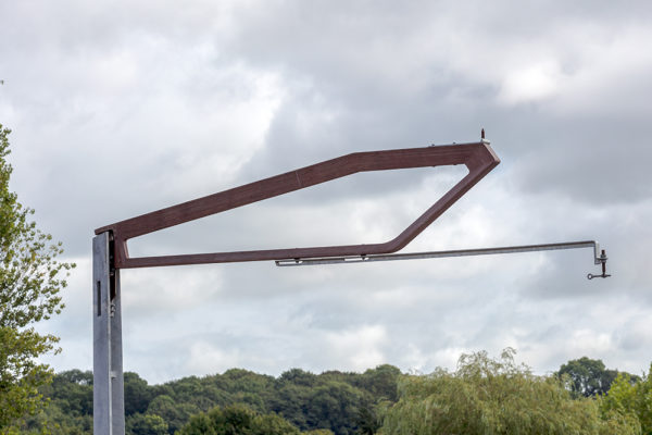
A prototype overhead line structure (OLS) designed to be quick to install, easy to maintain and more attractive to look at has been unveiled by its creators, Mott MacDonald and Moxon Architects.
Searching the Internet, I found this press release about the structure, which is entitled Moxon and Mott MacDonald unveil prototype for innovative Integrated Overhead Line Structure.
This picture is from the press release.
Various advantages are claimed.
- Reduced visual impact.
- Complete interoperability with existing overhead systems.
- Reduced number of components.
- Ease of installation.
- No additional engineer training.
- Reduced maintenance costs.
I like the concept, but is it too radical for Network Rail to give its blessing?
Perhaps the most radical feature is the use of laminated wood in the structure.
Conclusion
This is a very good design, but I doubt we’ll see it installed on UK railways.
Colne To Skipton Rail Line Re-Opening Campaign Moves Forwards
The title of this post, is the same as that of this article in the Lancashire Telegraph.
This is the first paragraph.
A meeting at the House of Commons hosted by Pendle MP Andrew Stephenson and his Labour counterpart for Keighley John Grogan convened senior officials from the Department of Transport (DfT), Transport for the North (TfN), Network Rail and commercial companies with an interest in East-West rail links.
Like many at the meeting, I feel very strongly that this link should be built.
There are obviously local reasons, like better passenger services between the conurbations of Blackburn/Accrington/Burnley and Leeds/Bradford, but there is something far more important.
Extra Train Paths Across The Pennines
Currently, trains take about twenty minutes between Rose Grove and Colne stations, over the mainly single track line.
I think it would be possible for experts to design a railway between Rose grove and Skipton stations via Colne, that would offer paths for three trains per hour (tph) across the Pennines in both directions. It might even be possible to accommodate four tph, using a combination of passing loops and digital signalling.
It should be noted that currently, the traffic through Accrington on the Calder Valley Line, which is to the West of Rose Grove station is around three tph in both directions. As the route is double-track, with modern trains and modern signalling, surely a higher frequency can be achieved.
These extra paths would be invaluable during the upgrading of the main TransPennine routes from Leeds to Manchester via Huddersfield.
I have some questions about the link.
Should The Link Be Double-Track?
Given that it will probably be difficult to put a double track on the Bank Top Viaduct over Burnley, I feel that to get the needed extra capacity, where it is possible to squeeze in a double-track, this should be done.
Should The Link Be Electrified?
Operationally, this would probably be preferable, but there are reasons why it could be difficult.
- There are a lot of quality stone bridges over all routes in the area.
- The heritage lobby might object to gantries marching across the Pennines.
- Network Rail’s abysmal performance on installing electrification.
It would also be sensible to electrify between Preston and Rose Grove stations, which would add substantially to the cost.
Passenger services wouldn’t be too much of a problem, as I am fairly certain that hydrogen-powered or battery trains could be used. The four-car Class 321 Hydrogen would probably by ideal.
Freight trains are probably better under electric power, rather than the awful Class 66 locomotives. Especially, if freight trains were run in the middle of the night.
I think the budget will decide on electrification.
Conclusion
I feel it is imperative, that to reduce the chaos of the TransPennine upgrade, work should start on the creation of the Skipton to Colne Link immediately.
Is This The Solution To A Charging Station For Battery Trains?
This page on the Opbrid web site has a main title of Automatic High Power Charging for Buses, Trucks, and Trains.
It also has a subtitle of Furrer+Frey Opbrid Charging Stations for Battery Trains.
Furrer + Frey are a Swiss railway engineering company, that design and build railway electrification systems.
The web page gives this introduction.
Since 2009, Furrer+Frey has developed a multi-modal ultra high power charging station for battery-powered vehicles that is already radically changing the way traction power is delivered to road and rail vehicles. In particular, the Furrer+Frey Railbaar system targets existing low traffic diesel traction routes as well as new light rail and tram projects. The technology applies to battery powered trams and trains (Railbaar), buses (Busbaar) and trucks (Trukbaar) with a design rooted in proven Swiss electric rail technology already successfully deployed by Furrer+Frey across Europe and the world.
The web page has an interesting image for a Swiss company.
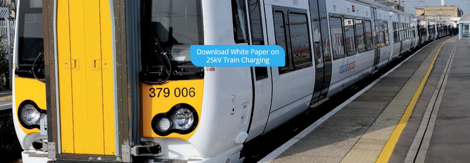
Shown is a Class 379 train, at a station, which I’m pretty sure is Cambridge.
Liverpool Street to Cambridge is a fully-electrified route, so why would a charging station be needed on this service?
I can’t think of a reason.
So I suspect, it’s just that to illustrate the web page, they needed to use a train that had the capability of running under battery power, which the Class 379 did in the BEMU trial of 2015.
It could also be that Furrer + Frey are working with Bombardier and it’s a Bombardier library picture.
But then Furrer + Frey probably work with all the major train manufacturers.
And as Bombardier have just released a new battery train, that I wrote about in Bombardier Introduces Talent 3 Battery-Operated Train, it would be logical that the two companies are working together, as battery trains will surely need charging in stations to develop longer routes.
Note the blue box in the middle of the picture. It says.
Download White Paper On 25 Kv Train Charging
If you download the white paper, you will find a very comprehensive and detailed description of how battery trains could be charged in stations. This is the introductory paragraph.
Battery-powered trains are rapidly becoming the vehicle of choice for the replacement of diesel
trains on non-electrified rail lines. Often there is not enough traffic on these lines to justify the expense of erecting overhead line equipment (OLE) along the track. In many cases, the train runs under OLE for part of its route where the battery train can charge via its pantograph. However, sometimes additional charging is required. While it is possible to erect additional kilometers of OLE for charging, it is more cost effective to charge the train via pantograph while stopped at a station using a very short length of overhead conductor rail and a 25 kV power supply.
I will now try to explain the solution.
The white paper gives this physical description of the solution.
The physical structure of the charging station is quite simple.
It consists of a short length of overhead conductor rail, approximately 20 m to 200 m in length. This length depends on the type, length, and number of battery trains that will be charging at one time. The conductor rail is supported by normal trackside posts and high voltage insulators. Insulated cables lead from the power supply to the conductor rail, with the return path from the running
rails. Furrer+Frey makes 25 kV and 15 kV overhead conductor rail systems that are ideal for this
purpose.
The design seems to use readily available components.
What Is Overhead Conductor Rail?
This picture, that I took on the Thameslink platforms at St. Pancras station, shows the overhead conductor rail, used to power the trains.
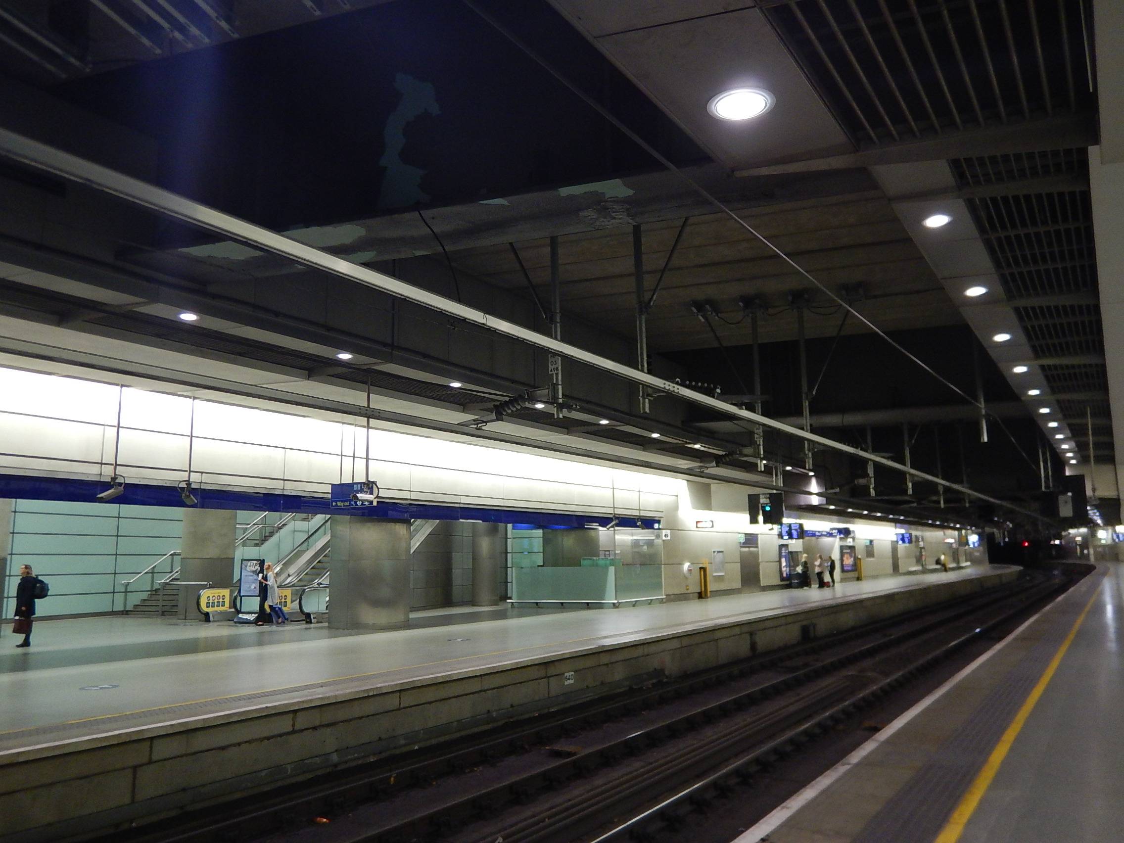
St. Pancras is one of the best places to see overhead conductor rail in London, although overhead conductor rail will be used by Crossrail in the tunnels.
How Would Overhead Conductor Rail Be Used To Charge A Train’s Batteries?
A short length of such a rail, would be mounted above the track in the station, so that it could be accessed by the train’s pantograph.
The rail would be positioned so that it was exactly over the train track, at the height required by the train.
What Voltage Would Be Used?
The normal overhead voltage in the UK, is 25 KVAC. There is no reason to believe that any other voltage would be used.
The overhead conductor rail/pantograph combination has a lot of advantages and benefits.
The Overhead Conductor Rail Is Standard
The overhead conductor rail is a standard Furrer + Frey product and it can be supported in any of the appropriate ways the company has used around the world.
This picture shows conductor rail fixed to the wall in Berlin HBf station.

Or it could be fixed to gantries like these at Gospel Oak station, which carry normal overhead wiring.
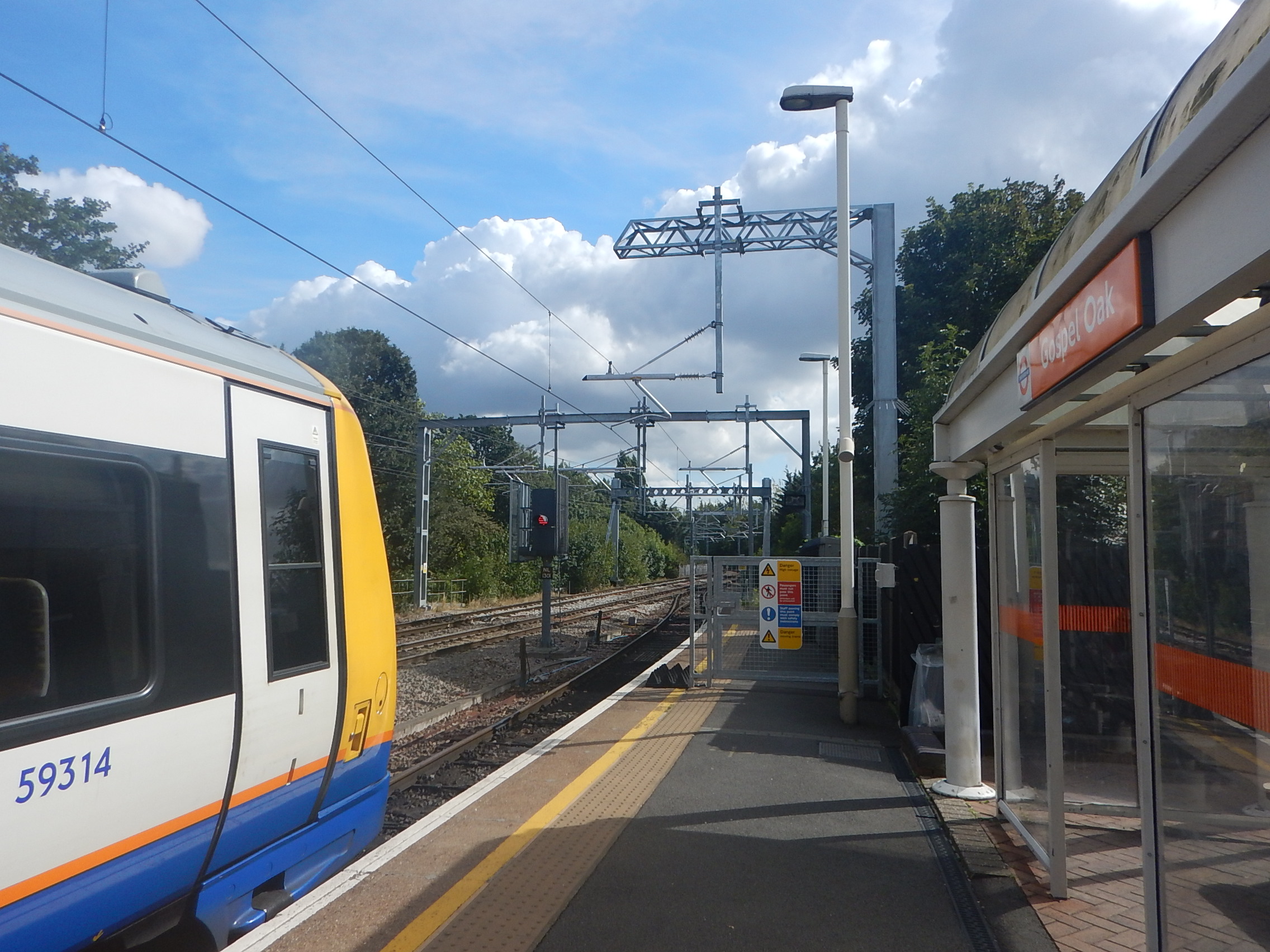
Note that gantries come in all shapes and sizes.
The Overhead Conductor Rail Can Be Any Convenient Length
There is probably a minimum length, as although drivers can stop the trains very precisely, a few extra metres will give a margin of error.
But there is no reason why at a through platform on a line served by battery trains, couldn’t have an overhead rail, that was as long as the platform.
The Train Pantograph Is Standard
The pantograph on the train, that collects the current from the overhead conductor rail can be an almost standard unit, as it will be doing the same job as it does on electrified sections of the route.
The white paper goes into this in detail.
As in the UK, our overhead line voltage is 25 Kv, the train can receive 1 MW with a current of 40 A, which is probably low enough to be below the limit of the conductor rail/pantograph combination. This would allow around 80 kWh to be transferred to the train in a five minute charge.
Could Trains Use Two Pantographs To Charge Batteries?
The white paper says that the system could handle more than one train, if the overhead conductor rail was long enough.
Bombardier’s Class 345 trains are effectively two half-trains, which each have their own pantograph.
So could a train use both pantographs to charge the batteries?
A Sophisticated Pantograph Control System Could Be Used
The train would probably have a sophisticated control system to automatically raise and lower the pantograph, so as to maximise the charge, whilst the train was in the station.
The System Should Be Safe
The overhead conductor rail would be no closer to passengers and staff, than overhead wires and conductor rail are at any other station platform in the UK.
I also suspect, that the power to the overhead conductor rail would only be switched on, if a train was being charged.
Standard Solutions Could Be Developed
One application of battery trains is to use them on a branch without electrification from an electrified line to a simple station in a town, housing or commercial development or airport..
The terminal stations would be very simple and surprisingly similar.
- One platform.
- An overhead conductor rail on gantries, a wall or some other simple support.
- A power supply for the overhead conductor rail.
A station building,, shelters and information displays could be added to the solution or designed specifically for the location.
Solutions for a wide range of countries would only differ in a few areas.
- The height of the platform.
- The gauge of the track.
- The overhead conductor rail voltage.
But I do believe that in this example of a standard system, there will be surprising commonality across the world.
As the white paper identifies, there is at least one tricky problem.
The High Voltage Power Supply
Providing high-quality, reliable high-voltage supplies may not always be that easy in some areas, so innovative electrical solutions will certainly be needed.
One solution suggested in the white paper involves using energy storage and then creating the 25 KVAC to power the overhead conductor rail.
I like this solution, as there are many applications, where these forms of independent power supplies are needed to power industrial premises, villages and equipment like flood pumps, often in remote locations. They could also incorporate a wind turbine or solar panels.
Someone will develop these systems and providing 15 or25 KVAC will be just another application.
Conclusion
I will add the conclusion from the white paper, as it says it all.
Battery trains are now available to replace diesel
trains on existing non-electrified tracks. They can
be charged using AC 25 kV 50 Hz or AC 15 kV 16,7
Hz either while running under catenary or when at
a standstill at a station using a short length of
overhead conductor rail and an appropriate power
supply. Standstill charging avoids the need to
build long stretches of catenary along a track
thereby saving money, and allowing the electrification
of track previously thought to be uneconomic
to electrify. Battery trains also enable the
use of renewable energy sources. Moving towards
green energy sources reduces harmful emissions
and noise which positively impacts climate change
and improves health
I am sure, we’ll see a lot of uses of this simple and efficient method of charging battery trains.
