Mott’s £6m Plan Approved For Hammersmith Bridge
The title of this post, is the same as that of this article on Construction Index.
This is the introductory paragraph.
Hammersmith & Fulham Council has approved a new plan to stabilise Hammersmith Bridge at significantly below the original expected cost, with works completing in less than a year.
Consulting engineer, Mott MacDonald have developed a solution to the bridge that is simple in the extreme.
This sentence describes the principle at the heart of the solution.
The Mott MacDonald solution involves the use of elastomeric bearings, which allow any pressure to be applied equally to all four corners while protecting the vulnerable 134-year-old cast iron structure.
There would also appear, that some very serious computing has been applied to allow the new bearings to be inserted, by just jacking up the bridge.
In addition to the cost and the speed of installation, the Mott MacDonald plan has been welcomed by Heritage England, will require less closures and doesn’t involve diversion of the gas main.
Conclusion
This intervention will stabilise the bridge and give time for a long-term solution to be developed, that will allow the bridge to be opened to vehicles.
BECCS Beats Hydrogen For Decarbonizing Steel In Europe: ArcelorMittal
The title of this post, is the same as that of this article on S & P Global Platts.
This is the first paragraph.
Bioenergy with carbon capture and storage (BECCS) offers a more cost-effective, readily available solution for decarbonizing the steel industry in Europe than clean hydrogen, steel producer ArcelorMittal’s head of strategy David Clarke said May 17.
So what do they mean by bioenergy?
To make iron from iron ore, you need a reducing agent like carbon or hydrogen.
Iron ore is rich in oxides of iron.
The carbon is usually some form of coal, which produces large amounts of carbon dioxide with the oxygen from the iron oxides.
Hydrogen produces lots of water with the oxygen.
David Clarke of ArcelorMittal explains the process in the article.
“We know biomass worked as a replacement for coal,” he said. “We’ve been using it in our operations in Brazil and other places for many, many years. We have a project in Belgium that we’ll be starting up next year using waste wood, using that to make bio-coal,” with a project to take the emissions from the bio-coal to produce bioethanol.
Is this a case of Back-To-The-Future? If I remember my history, didn’t Iron Age men use charcoal to smelt iron and other metal ores?
If those scientists from Velocys can make Sustainable Aviation Fuel and biodiesel from household waste and used disposable nappies, can they apply their magic to make bio-coal?
I see great cost advantages with this process, as surely it would enable existing blast furnaces to be used, provided they were fitted with carbon capture and storage.
Alternative Energy Storage Technologies To Challenge Electrochemistry
The title of this post, is the same as that of this article on Battery and Energy Storage Magazine.
It gives a good summary of two energy storage system; Highview Power and Gravitricity, that I rate highly promising.
It also gives details of a Danish system called Stiesdal Storage Technologies, which is developing a hot rocks energy storage system.
The article says this about the system.
The pumped-heat ESS uses pea-sized crushed basalt, rock in insulated steel tanks with the stored energy released by turbine.
SST CEO Peder Riis Nickelsen said: “The cost of crushed stone is at a totally different level per unit of energy than practically any other material for energy storage. Our charging and discharging system can utilise well-known technologies that have been applied for a century within other industries and are well-suited for mass production.”
The cost of materials is estimated to be €10 ($12) per kWh.
The first demonstration project, a 1-2MW, 24h capacity unit, will be installed at a power plant in Denmark next year, and will operate commercially.
This page on the Striesdal web site, explains the technology.
It sounds like the system uses very similar principles to Siemens Gamesa ETES, with a different heat storage medium.
Conclusion
At my last count, there now appears to be upwards of half-a-dozen viable alternatives to chemical batteries and traditional pumped storage. Some of the technologies are also backed, by large companies, organisations and countries, who can afford to take a long-term view.
I hope those, who claim that renewables will never power the world, have at least got the recipe for the cooking of humble pie ready.
MAN Energy Partners With Highview Power On Liquid-Air Energy-Storage Project
The title of this post, is the same as that of this article on Renewable Energy Magazine.
This is the introductory paragraph.
Highview Power, a leader in long duration energy storage solutions, has selected MAN Energy Solutions to provide its LAES turbomachinery solution to Highview Power for its CRYOBattery™ facility, a 50 MW liquid-air, energy-storage facility – with a minimum of 250MWh – located in Carrington Village, Greater Manchester , U.K.
The article is almost a word-for-word copy of this press release from MAN Energy Solutions, which has a similar title to this post and the Renewable Energy Magazine article.
As an Electrical Engineer who has done a lot of work in Project Management, I find these two paragraphs significant.
Construction will proceed in two phases. Phase 1 will involve the installation of a ‘stability island’, to provide near-instantaneous energy grid stabilisation. This will be achieved using a generator and flywheel, among other components. Enabling short-term stabilisation will provide the basis for Phase 2 and the completion of the more complex liquid air energy storage system that includes various compressors, air expanders and cryogenic equipment.
Phase 2 will represent the integration of stability services with a full-scale long-duration energy storage system, and in doing so promote the full integration of renewable energy. The Carrington project will offer a blueprint for future projects and cement the partnership between MAN Energy Solutions and Highview Power.
I first became acquainted with the use of flywheels to stabilise energy, when I was working in Enfield Rolling Mills as a vacation job at sixteen.
The centerpiece of their factory was a rolling mill, which took heated copper wirebars about two metres long amd ten centimetres square and rolled them into thick copper wire just a few millimetres in diameter. The mill was driven by a powerful electric motor, to which it was connected with a 97 tonne flywheel perhaps four metres in diameter in between. The flywheel spun at probably 3000 revolutions per minute.
The wirebar used to meander through the rolling mill several times and at each turn, the head would be caught by a man with a pair of tongs and turned back through the mill.
Each time the wire-bar went through a new pair of rolls the energy needed increased, as there was more rolling to do. So this extra energy was taken from the flywheel!
The rolling mill incidentally had been built by Krupp before the First World War. It still had the Krupp trademark of three interlocked railway tyres all over it. It had ended up in Enfield as reparations after the First World War. Enfield Rolling Mills added a fourth ring to create their own trademark.
It would appear that the kinetic energy of that flywheel could be as high as 1.6 MWh. Flywheels also react very fast.
Flywheel energy storage would appear to be a feasible intermediate energy store for this type of application.
I always remember Shimatovitch, who was the Chief Engineer of the company had jokingly once said that if the flywheel came off its bearings, it would have ended up a couple of miles away and would have demolished all the houses in its path. But he was a man with a dark sense of humour, who had spent most of the Second World War in a Nazi concentration camp.
Could it be that Phase 1 is the installation of a similar system to that I saw working in the 1960s, but upgraded with modern electronics, which exchanges power with the grid to create the stability island referred to in the press release.
In Phase 2 electricity can be passed to and from the CRYOBattery.
Looking at the MAN Energy Solutions web site, I suspect that they don’t care what sort of energy store they connect to the grid.
They would appear to be an excellent choice of engineering partner for Highview Power.
I also wonder how many other applications and customers, they will bring into the partnership.
Conclusion
This looks like a very sensible and low-risk strategy to connect the CRYOBattery to the grid.
Velocys Signs Agreement For Commercial-Scale Biomass-To-Jet Fuel In Japan
The title of this post, is the same as that of this article on the Chemical Engineer.
I am very hopeful about Velocys, who are a UK public company, that were spun out of Oxford University and do clever things in the area of chemical catalysts.
Velocys’ Fischer-Tropsch technology does seem to be a good way of creating sustainable aviation fuel from household rubbish and biomass.
Network Rail’s Big Push
The title of this press release on the Network Rail web site is 11,000 Tonne Tunnel To Be Installed On The Railway In First For UK Engineering.
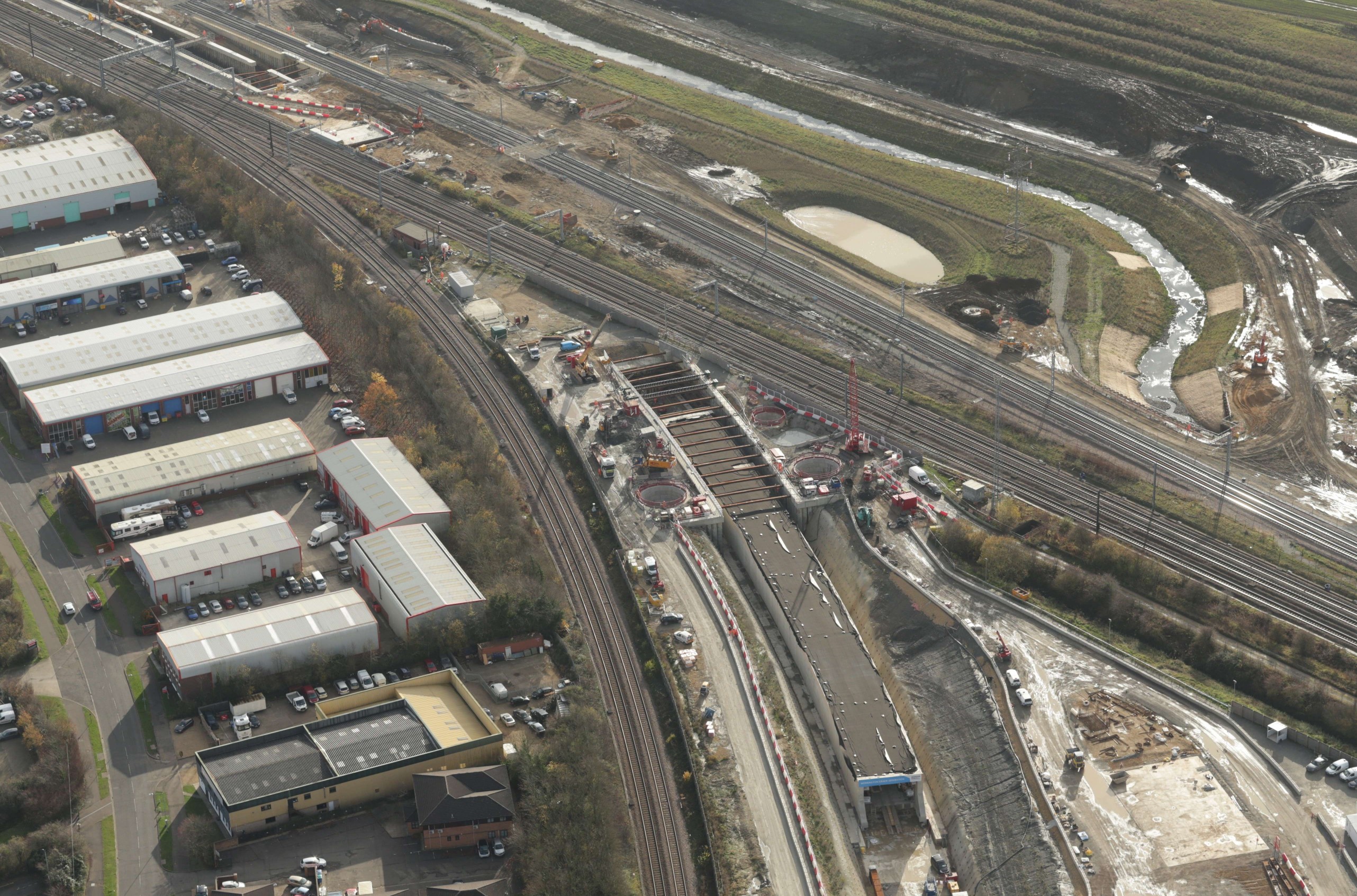
They have also released this aerial photograph of the tunnel, before it is pushed into place.
Note.
- The tunnel, which is just a curved concrete box is in the middle of the picture.
- To its left is the double-track Peterborough-Lincoln Line.
- Running across the far end of the tunnel are the multiple tracks of the East Coast Main Line.
- Peterborough is a few miles to the left, with the North to the right.
This Google Map shows the same area from directly above.

Note.
- The double-tracks of the Stamford Lines closest to the South-West corner of the map. These link the Peterborough-Birmingham Line to Peterborough.
- Next to them are the triple tracks of the East Coast Main Line.
- The third rail line is the double-track of the Peterborough and Lincoln Line.
- The new tunnel can be seen at the top of the map.
This map from Network Rail, shows the new track layout.
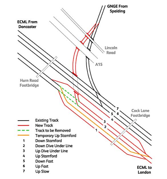
The map shows that the Stamford Line will divide with two tracks (1 and 4) going North to Stamford as now. Two new tracks (2 and 3) will dive-under the East Coast Main Line to join the existing Peterborough and Lincoln Line.
The tracks will run through the tunnel in the pictures, after it has been pushed under the East Coast Main Line.
- This will mean that the many freight trains between Peterborough and Lincoln will not have to cross the East Coast Main Line on the flat.
- This in turn could allow faster running of trains on the East Coast Main Line, that are not stopping at Peterborough.
This second Google Map shows the area to the North of the first map.
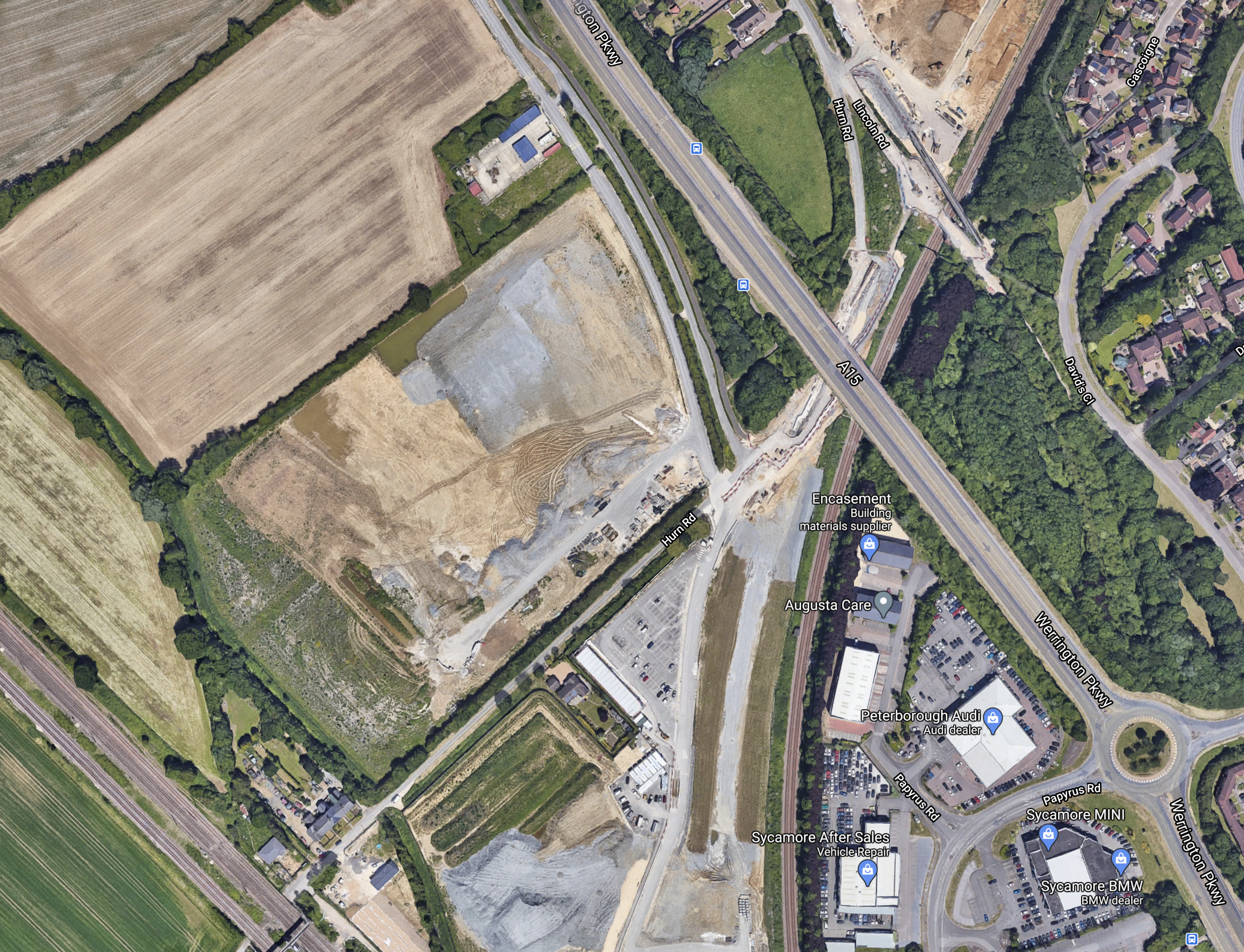
Note.
- The East Coast Main Line in the South-West corner of the map.
- The Peterborough and Lincoln Line curving from North-South across the map.
- A bridge would appear to be being constructed to take the A15 road over the new tracks, that will go through the tunnel.
- Another bridge will be constructed to take Lincoln Road over the new tracks.
It is certainly not a small project.
That is emphasised by this third Google Map, which is to the North of the previous map.
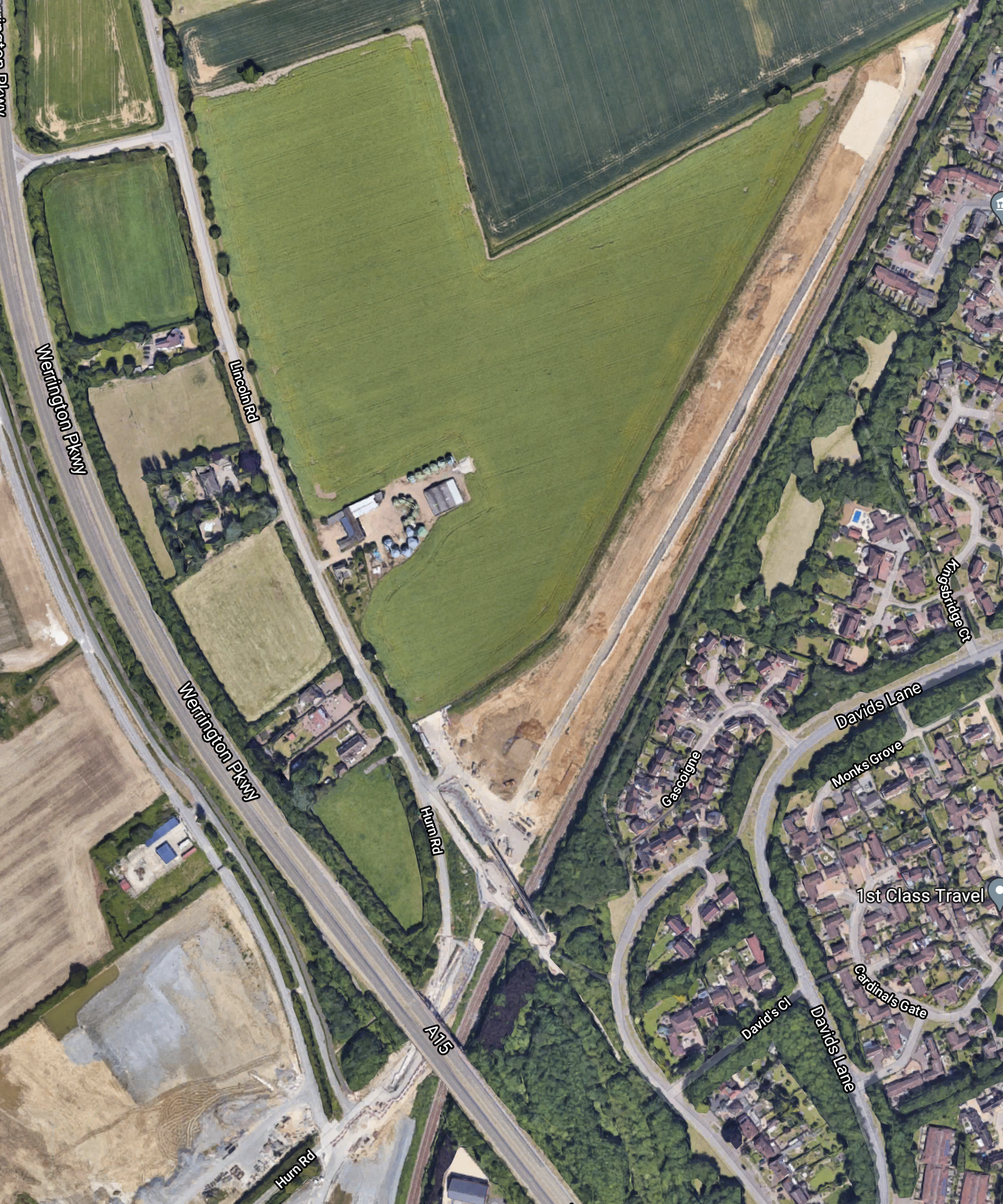
This map would appear to show space for more than a pair of tracks.
It looks to me, that space is being left for future rail-related development.
- Could it be for a small freight yard, where trains could wait before proceeding?
- If it were electrified, it could be where freight trains to and from London, switched between electric and diesel power.
- Could it be passing loops, so that freight trains can keep out of the way of faster passenger trains?
- Would it be a place for a possible new station?
If it is to be a full rail freight interchange, I can’t find any mention of it on the Internet.
The Big Push
Summarising, what is said in the press release, I can say.
- Major works to occur over nine days between 16 and 24 January
- It will be pushed at 150cm per hour.
- A reduced level of service will operate.
- It will take several weekends.
I hope it’s being filmed for later broadcasting.
Thoughts On Services
I have a few thoughts on passenger services.
London And Lincoln Via Spalding And Sleaford
Consider.
- Peterborough and Lincoln is 57 miles.
- The route has lots of level crossings.
- Much of the route between Peterborough and Lincoln has an operating speed of 75 mph
- There is a 50 mph limit through Spalding. Is this to cut down noise?
- Trains between Peterborough and Lincoln take a shortest time of one hour and twenty-three minutes, with four stops.
- Peterborough and Lincoln is 57 miles.
- This is an average speed of 41 mph.
I wonder what time a five-car Class 800 train would take to do the journey.
- At an average speed of 50 mph, the train would take 68 minutes and save 15 minutes.
- At an average speed of 60 mph, the train would take 57 minutes and save 26 minutes.
- At an average speed of 70 mph, the train would take 49 minutes and save 18 minutes.
As the fastest London Kings Cross and Peterborough time is 46 minutes, this would mean that with an average speed of 60 mph, a time between London Kings Cross of one hour and forty-three minutes could be possible.
- There could be additional time savings by only stopping at Peterborough, Spalding and Sleaford.
- The Werrington Dive Under looks to be built for speed and could save time.
- If the 50 mph limit through Spalding is down to noise, battery electric trains like a Hitachi Intercity Tri-Mode Battery Train might be able to go through Spalding faster.
- Could some track improvements save time between Peterborough and Lincoln?
As the fastest journeys via Newark to Lincoln take one hour and fifty-six minutes, it looks to me, that LNER might be able to save time by going via Spalding and Sleaford after the Werrington Dive Under opens.
London And Skegness
If there were a fast London train from Sleaford, it will take under an hour and thirty minutes between London Kings Cross and Sleaford.
- Currently, the connecting train between Skegness and Sleaford takes an hour for the forty miles.
- The service is currently run by Class 158 trains.
- With some 100 mph trains on the Skegness and Sleaford service, it might be possible to travel between London and Skegness in two hours and fifteen minutes with a change at Sleaford.
There would appear to be possibilities to improve the service between London and Skegness.
Lincoln And Cambridge
I used to play real tennis at Cambridge with a guy, who was a Cambridge expansionist.
He believed that Cambridge needed more space and that it should strongly rcpand high-tech research, development and manufacturing all the way across the fens to Peterborough and beyond.
I listened to his vision with interest and one thing it needed is a four trains per hour express metro between Cambridge and Peterborough.
- Ely and Peterborough should be electrified for both passenger and freight trains.
- March and Spalding should be reopened.
- Cambridge has the space for new services from the North.
Extending the Lincoln and Peterborough service to Cambridge could be a good start.
Conclusion
The Werrington Dive Under will certainly improve services on the East Coast Main Line.
I also feel, that it could considerably improve rail services between London and South Lincolnshire.
It certainly looks, like Network Rail have designed the Werrington Dive Under to handle more traffic than currently uses the route.
Towns like Boston, Skegness, Sleaford and Spalding aren’t going to complain.
Engineers Go Microbial To Store Energy, Sequester CO2
The title of this post, is the same as that of this article on the Cornell Chronicle.
This is the first two paragraphs.
By borrowing nature’s blueprints for photosynthesis, Cornell bioengineers have found a way to efficiently absorb and store large-scale, low-cost renewable energy from the sun – while sequestering atmospheric carbon dioxide to use later as a biofuel.
The key: Let bioengineered microbes do all the work.
This is slave labour, that even the most ardent of Human and Animal Rights activists would approve.
This is technology to watch!
H2U Eyre Peninsula Gateway Hydrogen Project Begins Largest Green Ammonia Plant
The title of this post, is the same as that of this article on Hydrogen Fuel News.
- South Australia will be creating the largest green ammonia plant in the world.
- It will make 40,000 tonnes of green ammonia every year.
- The plant will be powered totally by renewable energy.
- At its heart will be a 75 MW hydrogen electrolyser.
This paragraph sums up the main objective of the plant.
According to Dr. Attilio Pigneri, H2U CEO, the project will play an important role in the ongoing development of the emerging green hydrogen and green ammonia markets.
It appears a lot of the green ammonia will be exported to Japan.
What Is Green Ammonia?
It is just ammonia produced by renewable energy. This is the first paragraph of the Wikipedia entry for ammonia.
Ammonia is a compound of nitrogen and hydrogen with the formula NH3. A stable binary hydride, and the simplest pnictogen hydride, ammonia is a colourless gas with a characteristic pungent smell. It is a common nitrogenous waste, particularly among aquatic organisms, and it contributes significantly to the nutritional needs of terrestrial organisms by serving as a precursor to food and fertilizers. Ammonia, either directly or indirectly, is also a building block for the synthesis of many pharmaceutical products and is used in many commercial cleaning products. It is mainly collected by downward displacement of both air and water.
It is a very useful chemical compound and it is now being developed as a zero-carbon fuel, as I wrote in The Foul-Smelling Fuel That Could Power Big Ships.
It can also be used as a refrigerant.
One of the most amazing pieces of engineering, I ever saw was a very old barn, where a farmer stored vast tonnages of apples. It was kept cool, by a refrigeration plant certainly built before the Second World War or possibly even the First, which used ammonia as the refrigerant.
Now that’s what I call engineering!
Rolls-Royce signs MoU With Exelon For Compact Nuclear Power Stations
The title of this post, is the same as that of this press release on the Rolls-Royce web site.
These are the first two paragraphs.
Rolls-Royce and Exelon Generation have signed a Memorandum of Understanding to pursue the potential for Exelon Generation to operate compact nuclear power stations both in the UK and internationally. Exelon Generation will be using their operational experience to assist Rolls Royce in the development and deployment of the UKSMR.
Rolls-Royce is leading a consortium that is designing a low-cost factory built nuclear power station, known as a small modular reactor (SMR). Its standardised, factory-made components and advanced manufacturing processes push costs down, while the rapid assembly of the modules and components inside a weatherproof canopy on the power station site itself avoid costly schedule disruptions.
This is the first paragraph of the Wikipedia entry of Exelon.
Exelon Corporation is an American Fortune 100 energy company headquartered in Chicago, Illinois and incorporated in Pennsylvania. It generates revenues of approximately $33.5 billion and employs approximately 33,400 people. Exelon is the largest electric parent company in the United States by revenue, the largest regulated electric utility in the United States with approximately 10 million customers, and also the largest operator of nuclear power plants in the United States and the largest non-governmental operator of nuclear power plants in the world.
These two paragraphs from the press release flesh out more details.
The consortium is working with its partners and UK Government to secure a commitment for a fleet of factory built nuclear power stations, each providing 440MW of electricity, to be operational within a decade, helping the UK meet its net zero obligations. A fleet deployment in the UK will lead to the creation of new factories that will make the components and modules which will help the economy recover from the Covid-19 pandemic and pave the way for significant export opportunities as well.
The consortium members feature the best of nuclear engineering, construction and infrastructure expertise in Assystem, Atkins, BAM Nuttall, Jacobs, Laing O’Rourke, National Nuclear Laboratory, Nuclear Advanced Manufacturing Research Centre, Rolls-Royce and TWI. Exelon will add valuable operational experience to the team.
This is not what you call a small deal.
This is the last section of the press release.
By 2050 a full UK programme of a fleet of factory built nuclear power stations in the UK could create:
- Up to 40,000 jobs
- £52BN of value to the UK economy
- £250BN of exports
The current phase of the programme has been jointly funded by all consortium members and UK Research and Innovation.
But that is not all, as there is also a second press release, which is entitled Rolls-Royce Signs MoU With CEZ For Compact Nuclear Power Stations.
These are the first two paragraphs.
Rolls-Royce and CEZ have signed a Memorandum of Understanding to explore the potential for compact nuclear power stations, known as small modular reactors (SMR), to be built in the Czech Republic.
Rolls-Royce is leading the UK SMR Consortium that is designing this type of low-cost nuclear power station. Its standardised, factory-made components and advanced manufacturing processes push down costs; and the rapid assembly of the modules inside a weatherproof canopy at the power station site itself speeds up schedules.
These are my thoughts.
What Is A Small Modular Reactor or SMR?
This is the first paragraph of the Wikipedia entry for Small Nuclear Reactor.
Small modular reactors (SMRs) are a type of nuclear fission reactor which are smaller than conventional reactors. This allows them to be manufactured at a plant and brought to a site to be assembled. Modular reactors allow for less on-site construction, increased containment efficiency, and enhanced safety due to passive nuclear safety features. SMRs have been proposed as a way to bypass financial and safety barriers that have plagued conventional nuclear reactors.
This section on Wikipedia gives more details of the Rolls-Royce SMR.
Rolls-Royce is preparing a close-coupled three-loop PWR design, sometimes called the UK SMR.] The power output is planned to be 440 MWe, which is above the usual range considered to be a SMR. The design targets a 500 day construction time, on a 10 acres (4 ha) site. The target cost is £1.8 billion for the fifth unit built.
The consortium developing the design is seeking UK government finance to support further development. In 2017 the UK government provided funding of up to £56 million over three years to support SMR research and development. In 2019 the government committed a further £18 million to the development from its Industrial Strategy Challenge Fund.
The construction time, site size and cost make for one of the big advantages of SMRs.
Say you need to create a 3260 MW nuclear power station like Hinckley Point C.
- This would need a fleet of eight 440 MW SMRs.
- These would cost £14.4 billion
- Wikipedia lists Hinkley Point C as costing between £21.5 billion and £ 22.5 billion.
- I suspect there will be an adjustment for the connection to the National Grid, which is probably included in the Hinckley Point C figures.
- Eight SMRs will occupy 80 acres.
- Hinckley Point C will occupy 430 acres.
- Hinckley Point C was planned to be built in seven years.
- Eight SMRs built one after the other would take 11 years. But, they would probably be planned to be built in an optimal way, where reactors came on-line, when their power was needed.
The biggest advantage though, is that as each of the eight SMRs is commissioned, they can start supplying power to the grid and earning money. This means that financing is much easier and the first reactor helps to pay for its siblings.
Could An SMR Replace A Fossil Fuel Power Station?
Suppose you have a coal-fired power station of perhaps 800 MW.
The power station will have a connection to the grid, which will be able to handle 800 MW.
If the power station is closed, there is no reason, why it can’t be replaced by an appropriately-sized fleet of SMRs, provided the site is suitable.
Who Are TWI?
I would assume that TWI is The Welding Institute, who are described like this in their Wikipedia entry.
The Welding Institute (TWI) is a research and technology organisation, with a specialty in welding. With headquarters six miles south of Cambridge, Cambridgeshire, England, since 1946, and with facilities across the UK and around the world. TWI works across all industry sectors and in all aspects of manufacturing, fabrication and whole-life integrity management technologies.
It strikes me, this organisation could be a very important part of the consortium.
Memories Of Althorpe
On The way to Cleethorpes, I passed through Althorpe station.

This Google Map shows the area.
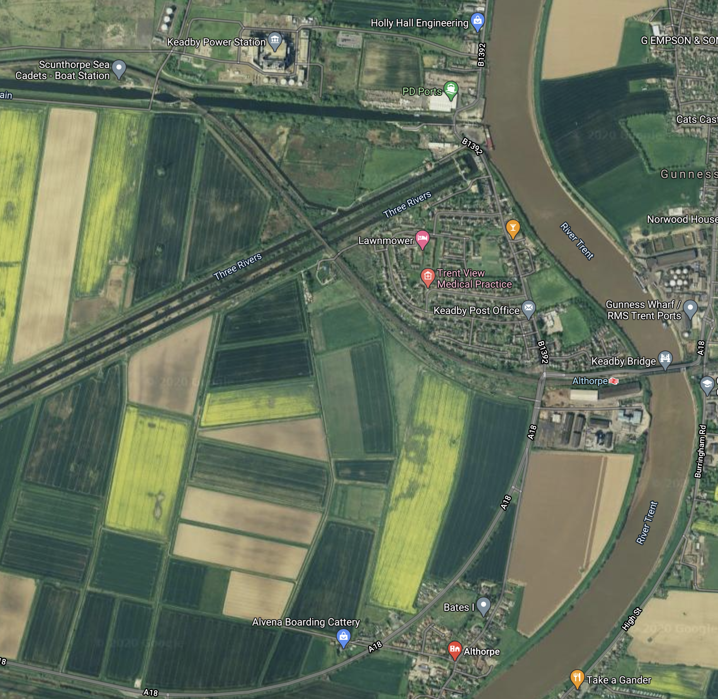
Note.
- The River Trent flowing South to North.
- Keadby power station at the top of the map.
- Althorpe station close to the bridge over the river.
- The village of Althorpe is at the South of the map by the river.
C and myself had friends, who farmed much of the land in the curve of river, South of the railway.
These are a few tales, some might enjoy.
Althorpe And Princess Diana’s Grave
I was once told, that regularly tourists would appear looking for the last resting place of Princess Diana.
Sat-navs may be a wonderful gadget for some, but they do lead those with a certain lack of common sense on wild goose chases.
C And The Tug-Boats
C once spent a night in their farmhouse, which was by the River Trent.
She didn’t sleep well, as tug-boats pulling barges were constantly going past and sounding their sirens. The river was actually above the house, due to the embankments to stop flooding.
Princess Anne And The Centrefold
Our friends’ daughter was a very good rider in eventing and used to supplement her variable income in the sport with modelling. At one point, I used her for some promotional shots for one of my companies.
Some years ago, she was competing at an event in Yorkshire. Coincidentally, this was just after she had appeared as the centrefold in a well-known men’s magazine.
The event was a bit of a nightmare for her, as paparazzi were following her with open copies of the magazine.
At one point, it all got a bit much, so she decided to sneak back to the calm of her horsebox, by a circuitous route.
As she walked back, she encountered Princess Anne, who was also competing and using the same route to avoid the paparazzi.
They talked about the pressures of the paparazzi, who were being a nuisance, with the Princess saying, she approved of my friends’ daughter’s modelling and hoped it continued, as it had taken the pressure off herself.
Flixborough
My friends’ farm was not far from Flixborough, which is infamous for the Flixborough Disaster in 1974, when a chemical plant exploded and killed 28 people and seriously injured a further 36.
My friends also lost several thousand pigs because of the explosion.
Wikipedia says this about the cause of the explosion.
The disaster involved (and may well have been caused by) a hasty modification. There was no on-site senior manager with mechanical engineering expertise (virtually all the plant management had chemical engineering qualifications); mechanical engineering issues with the modification were overlooked by the managers who approved it, nor was the severity of the potential consequences of its failure appreciated.
At the time, I had just left ICI and I was still in contact with my former colleagues.
One told me, that he had met a Senior ICI Engineer, who had been involved with the enquiry into the disaster.
The plant had been a copy of a Dutch plant, that had been built to metric units, which were converted to Imperial to build the Flixborough plant.
As ICI had used metric units since the mid-1950s, there was considerable alarm in the mind of the Senior Engineer, that when the hasty modification was made, someone got mixed up.
Would the Flixborough disaster have happened, if the plant had been built as a copy of the Dutch plant using metric units?

