Battery Train And Fast Charger To Be Tested In London
The title of this post is the same as that of this article on Railway Gazette.
This is the first paragraph.
Great Western Railway has signed an agreement to test Vivarail’s Class 230 battery multiple-unit and fast charging technology under real-world conditions on the 4 km non-electrified branch between West Ealing and Greenford in West London.
As an engineer, who started designing control systems for rolling mills in the mid-1960s and went on to get a Degree in Control and Electrical Engineering from Liverpool University, before working for ICI applying computers to a variety of problems, I can’t look at a railway line like the Greenford Branch without wanting to automate it.
I had one amateurish attempt in An Automated Shuttle Train On The Greenford Branch Line. I was trying to get four trains per hour (tph) on the branch and I don’t think that is possible, with the Class 230 trains.
Now we know the train we are dealing with, I could plan an automated system, that would drive the train.
- Each journey on the branch takes around 11-12 minutes.
- Two tph would take between 44 and 48 minutes shuttling between the two stations in an hour.
- The article states that recharging takes ten minutes.
- If the train charged the batteries once per hour, that would leave between two and six minutes for the other three stops.
- Any freight train using the branch seems to take about six minutes, so they could sneak through, when the shuttle is having a fast charge.
- I would also use a similar system to that originally used on the Victoria Line. After the driver has closed the doors and ascertained that there were no problems, they would press a button to move the train to the next station and then automatically open the doors.
From this rough calculation to run a two tph service, I suspect that the train needs to be able to go between West Ealing and Greenford stations in ten minutes. Assuming one ten minute Fast Charge per hour, this would give three minutes and twenty seconds to turn the train, at the three terminal station stops.
I certainly feel, that an automatic shuttle would be possible.
A Lower-Cost Pumped Hydro Storage System
Whilst writing some of the posts recently about pumped storage I came across the Loch Sloy Hydro-Electric Scheme.
This is the introductory sentence in Wikipedia.
The Sloy/Awe Hydro-Electric Scheme is a hydro-electric facility situated between Loch Sloy and Inveruglas on the west bank of Loch Lomond in Scotland.
This page on the Greenage web site gives comprehensive details of the power station and is well worth a read.
This Google Map shows the Lochs Sloy and Lomond.
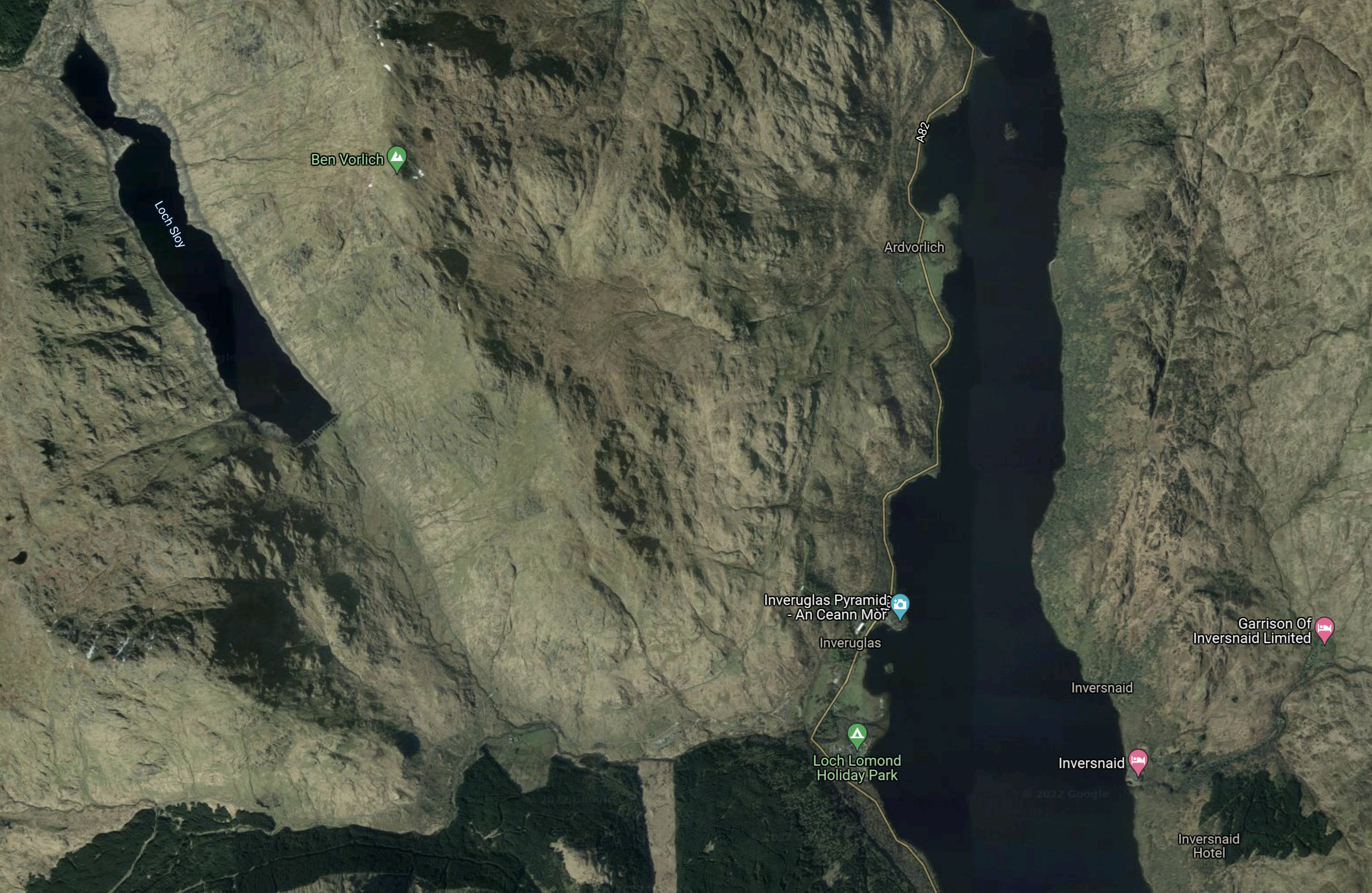
Note.
- Loch Sloy is in the North-West corner of the map.
- The page on Greenage says that Loch Sloy can store 14 GWh of electricity
- Loch Lomond is the body of water towards the Eastern side of the map.
- Inverglas is on the West bank of Loch Lomond to the North of the Loch Lomond Holiday Park, which is indicated by the green arrow with a tent.
This second Google Map shows the power station and Inverglas.
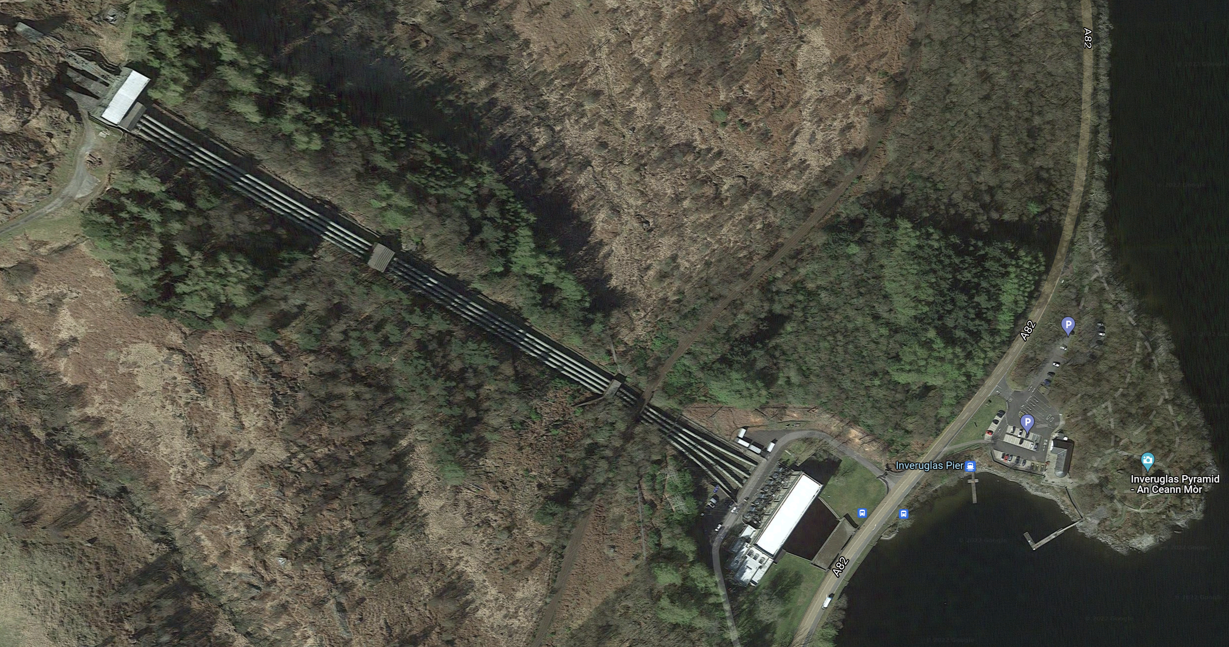
Note.
- It is a classic layout for a hydro-electric power station.
- In the North West corner of the map is the valve house, which is connected to Loch Sloy by a three kilometre tunnel.
- The valve house controls the water flows to the power station by Loch Lomond.
- There are four two-metre pipes running down the hill, one for each of the four turbines.
- According to the page on Greenage, the power station has three 40 MW turbines and one 32 MW turbine, which gives a total output of 152 MW.
- The water discharges into Loch Lomond after doing its work in the power station.
Loch Sloy is the largest conventional hydroelectric power plant in the UK.
Extending The Loch Sloy Hydro-Electric Scheme
This page on Hydro Review, which is dated the 10th of November 2010, is entitled SSE Gets Government Consent For Sloy Pumped-Storage Hydropower Project.
These are the first paragraph.
SSE Generation Ltd., the wholly owned generation business of Scottish and Southern Energy, has received consent from the Scottish Government to develop a 60-MW pumped-storage hydro project at its existing Sloy hydropower station at Loch Lomond, SSE reported.
Note.
- Two 30 MW pumps will be added to the power station to pump water up the hill from Loch Lomond to Loch Sloy.
- According to the page on Greenage, if the two pumps worked together for six hours, they would transfer 432,000 m3 of water. Note that a cubic metre of water weighs a tonne.
- Water would be transferred, when there was a surplus of energy being generated over the demand.
It would appear to be a simple scheme, as it is just adding two pumps to pump the water up the hill.
- As pumps rather than pump/turbines as at Foyers are used, there is no corresponding increase in generating capacity.
- Water also appears to be pumped up to the valve house in the existing pipes.
- Loch Sloy and Loch Lomond would not need major works to enable the scheme..
The page on Greenage gives the cost at just £40 million.
Originally, the project was supposed to have started in 2012, but as there are environmental problems with the fish, the work has not started.
These problems are detailed on the page on Greenage.
Conclusion
For £40 million, 14 GWh of pumped storage can be created at Sloy.
- But it could be bigger than 14 GWh, as this page on the Strathclyde University web site, says 20.4 GWh is possible.
- This would surely, be a project that could be first in the queue, once the environmental problems are solved.
20 GWh of pumped storage would be nice to have reasonably quickly.
Does London Need High Capacity Bus Routes To Extend Crossrail?
If Crossrail has a major problem, it is that some areas of the capital will find it difficult to access the new line.
Up to the age of sixteen, I used to live half-way between Oakwood and Cockfosters stations on the Piccadilly Line.
There are a large number of people who live along the Northern reaches of the Piccadilly Line, who might want to use Crossrail to perhaps go to Heathrow or places in East London.
But the journey will need a double change as there is no interchange between the Piccadilly Line and Crossrail.
I suspect that many will link to Crossrail by taking the Piccadilly Line to Wood Green, Turnpike Lane or Manor House and then get a 141 bus to Moorgate. It is a route, I use if I want to go to Southgate or Cockfosters from my house, which has a 141 stop opposite.
But then as a child to go to Harringay, where my father had an uncle, my mother would use a 641 trolley bus from Wood Green or Turnpike Lane.
Do people follow the public transport habits of their parents?
I know I do!
My father never went on a deep tube. As he several times mentioned the terrible Bank station bombing in the Blitz, which killed 56 people, I always thought that was his problem. But now living as I do along the Northern and Northern City Lines, I suspect it was more to do with air quality, as we were or are both bad breathers.
I suspect that when Crossrail opens, the 141 bus will be heavily used by travellers going between the Northern reaches of the Piccadilly Line and Crossrail at Moorgate.
The 141 bus goes between London Bridge station and Palmers Green and it has a route length of about nine miles.
Currently, buses run every fifteen minutes or so, but I doubt it will be enough in future as Transport for London are rerouting the closely-related 21 bus.
I suspect any route seen as an extension of Crossrail needs to have the following characteristics.
- High frequency of perhaps a bus every ten minutes.
- Interior finish on a par with the Class 345 trains.
- Wi-fi and phone charging.
I would also hope the buses were carbon-free. Given that some of these routes could be quite long, I would suspect hydrogen with its longer range could be better.
Other Routes
According to me, the 141 bus route needs improvement!
But how many other routes could need similar improvement?
ILI Group Announces New 1.5GW Pumped Storage Hydro Project
The title of this post is the same as that of this article on Insider.
This is the body of the article.
Intelligent Land Investments Group (ILI) has commenced the initial planning phase for its new 1.5 GigaWatt (GW) pumped storage hydro (PSH) project, Balliemeanoch, at Loch Awe in Argyll & Bute.
This is ILI’s third and largest PSH project. Its other PSH projects include ‘Red John’ at Loch Ness, which was awarded planning consent from Scottish Ministers in June Last year, and ‘Corrievarkie’ at Loch Ericht for which they aim to submit a Section 36 planning application in August.
The new project would be able to supply 1.5GW of power for up to 30 hours, enough to power 4.5 million homes.
The project will create a new head pond in the hills above Loch Awe capable of holding 58 million cubic metres of water when full and it is estimated the project will offset more than 200 million tonnes of CO2 emissions over its lifetime.
I would assume that this will be a privately-financed project and at 45 GWh it will be one of the largest pumped storage systems in the world.
But it must show that if it is privately-financed that the big boys in infrastructure finance, see pumped storage as a safe place to put insurance and pension funds to earn a worthwhile return.
- No-one’s going to steal one of these systems.
- They are a job-creating asset when built.
- Hydro-electric power seems very safe, when well-built.
- You don’t see media reports of schemes like Cruachan, Electric Mountain and Foyers breaking down.
In World’s Largest Wind Farm Attracts Huge Backing From Insurance Giant, I talked about Aviva’s funding for wind farms. If Aviva wukk fund those, surely they’ll fund schemes like this, as it could be argued that they make wind farms a better investment and more valuable, as they won’t have to shut down so often, when there’s too much power.
The Development Of The Foyers Pumped Storage Scheme
This leaflet from SSE Renewables probably gives as good a record as any others about the development of the Foyers Pumped Storage Scheme.
This is the introduction.
The Foyers Scheme is a 300 Megawatt (MW) combined conventional hydro and pumped storage scheme. 1896 saw the British Aluminium Company commission Foyers for the smelting of aluminium. The plant was in continuous operation for 70 years until it’s closure in 1967. The scheme was promoted by NOSHEB in February 1968 and after receiving statutory approval in April 1969 work started that autumn and was commissioned in 1975 . The high level reservoir is Loch Mhor which was formed under the original development by enlarging and joining Loch Garth and Loch Farraline.
The full catchment area of Loch Mhòr today is now 207 sq km.
Note that NOSHEB stands for North of Scotland Hydro Electric Board.
This Google Map shows Loch Mhòr.
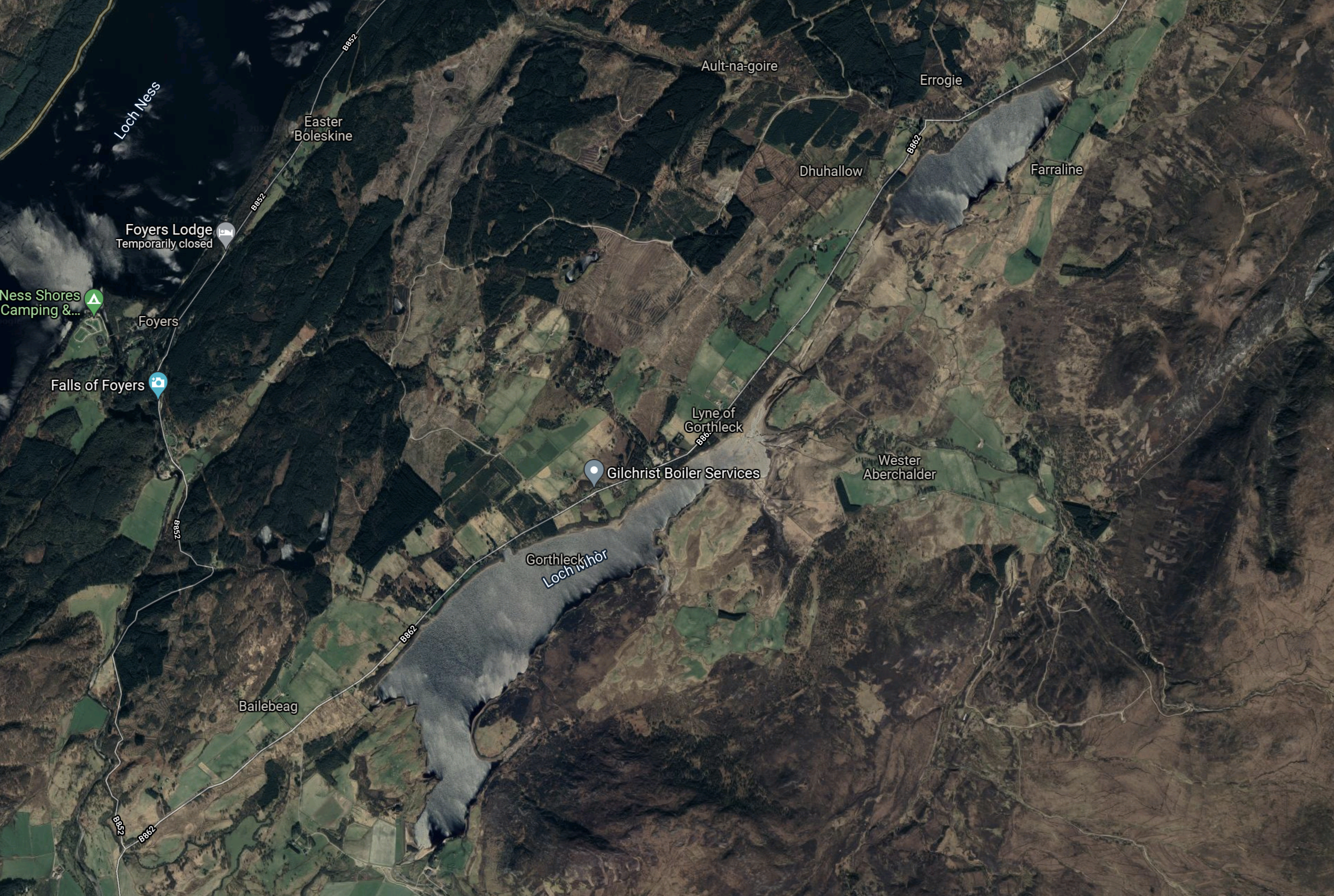
Note.
- Loch Ness is in the North West corner of the map.
- Loch Mhòr is the loch running diagonally across the map.
- Loch Mhòr was originally two separate lochs; Loch Garth in the South-West and Loch Farraline in the North-East.
- The power station is on the shores of Loch Ness.
I have found a document on the Internet, that says that the current storage capacity of Loch Mhòr is 10 GWh. That figure, if it is correct, would make the Foyers pumped storage scheme a small amount bigger than Electric Mountain.
The Original Scheme
The original scheme appears to have been a straight hydro-electric scheme with the water running from Loch Mhòr into Loch Ness through turbines. I don’t know how big it was and if anybody does, the figure needs to be inserted in this post. So if you know it, please tell me!
This gazetteer gives the figure at 3750 kW and also this history.
The British Aluminum Company development at Foyers was the first large-scale use of hydropower in Scotland. The scheme was highly influential, proving not only the viability of the technology to produce electricity with water driven turbines, but also that the power could be successfully applied to industrial processes. The British Aluminum Company went on to develop two large smelters in Scotland at Kinlochleven and Lochaber.
The original scheme generated electricity for seventy years.
The Current Scheme
There are effectively two parts of the current scheme, which was created in the early 1970s.
- The original 3.7 MW turbines have been replaced by a 5 MW turbine in the old power station.
- A new separate pumped storage power station has been built with two 150 MW pump/turbines.
This paragraph from the leaflet from SSE Renewables, gives brief details of the engineering.
When the station is generating, water flows from Loch Mhor through 2 miles of tunnels and shafts to the power station. When pumping, energy is drawn from the main transmission system at times of low load to drive the two 150 megawatt machines in the reverse direction and pump water from Loch Ness up to Loch Mhor. The existing gravity dam at the outlet of Loch Mhor (231.7m long and 9.14m high) was retained by NOSHEB . Remedial work was carried out on subsidiary earth embankment dams. The waters of the River Fechlin are diverted into Loch Mhor by a tunnel and the channel of the river.
From the complete description in the leaflet, it looks to be sound engineering.
Did Modern Project Management Enable This Scheme?
As someone, who was involved in writing project management software from about 1972, I do wonder if the arrival of ,odern project management around the mid-1960s was one of factors that prompted NOSHEB to carry out this scheme.
Other factors would have been.
- The original turbines were on their last legs after seventy years of generating electricity.
- There was a need for more pumped storage.
- This scheme was feasible.
I would very much like to meet one of the engineers and talk the scheme through.
Conclusion
This power station and its rebuilding as a pumped storage scheme has been carried out to an excellent standard and I wonder if similar techniques can be used to create new pumped storage systems around the world.
A Plea From Michael Portillo
In the latest episode of his Great British Coastal Railways – Helensburgh to Connel, Michael Portillo made a plea to train makers.
Travelling along the scenic West Highland Line, he asked train manufacturers to build a train with a glass roof.
Should The Great Northern And Great Eastern Joint Line Be Electrified?
The Great Northern And Great Eastern Joint Line was created in the Nineteenth Century by the Great Northern Railway and the Great Eastern Railway.
- The main purpose was to move freight like coal, agricultural products and manufactured goods between Yorkshire and Eastern England.
- It originally ran between Doncaster and Huntington via Gainsborough, Lincoln, Sleaford, Spalding and March.
- It had a full length of almost 123 miles.
- There was a large marshalling yard at Whitemoor near March.
Over the years the line has been pruned a bit and now effectively runs between Doncaster and Peterborough.
- Trains between Lincoln and March are now routed via Peterborough.
- It carries upwards of twenty freight trains per day in both directions through Lincoln Central station.
- Many of the freight trains are going to and from the East Coast ports.
- The distance between Doncaster and Peterborough is 93.7 miles, as opposed to the 79.6 miles on the East Coast Main Line.
- The line is not electrified, but it connects to the electrified East Coast Main Line at both ends.
There have been some important developments in recent years.
2015 Freight Upgrade
Wikipedia says this about the major 2015 freight upgrade.
In 2015 a £280 million upgrade of the Joint Line by Network Rail was substantially complete, enabling two freight trains per hour to be diverted from the congested East Coast Main Line; gauge enhancements to enable the passage of 9 ft 6 in (2.90 m) containers were included in the work.
The Sleaford avoiding line had been substantially downgraded since the 1980s and was reinstated to double track as part of the 2015 scheme. Resignalling and modernisation of level crossings was included.
This means that freight trains have an alternative route, that avoids the East Coast Main Line.
Doncaster iPort
Over the last few years the Doncaster iPort has been developed, which is an intermodal rail terminal.
- It has a size of around 800 acres.
- The site opened in early 2018.
- There is a daily train to the Port of Southampton and two daily trains to both Teesport and Felixstowe.
- The Felixstowe trains would appear to use the Joint Line.
I feel that as the site develops, the Doncaster iPort will generate more traffic on the Joint Line.
This Google Map shows the Doncaster iPort.

There would appear to be plenty of space for expansion.
The Werrington Dive Under
The Werrington Dive Under has been built at a cost of £ 200 million, to remove a bottleneck at the Southern end of the Joint Line, where it connects to the East Coast Main Line.
The Werrington Dive Under was built, so that it could be electrified in the future.
LNER To Lincolnshire
LNER appear to have made a success of a one train per two hours (tp2h) service between London King’s Cross and Lincoln station.
- LNER have stated, that they want to serve Grimsby and Cleethorpes in the North of the county.
- North Lincolnshire is becoming important in supporting the wind energy industry in the North Sea.
- Lincoln is becoming an important university city.
- Several towns in Lincolnshire probably need a service to Peterborough and London.
- In 2019, the Port of Grimsby & Immingham was the largest port in the United Kingdom by tonnage.
I can see an expanded Lincolnshire service from LNER.
Full Digital Signalling Of The East Coast Main Line To The South Of Doncaster
This is happening now and it will have a collateral benefits for the Joint Line.
Most passenger and freight trains will also use the East Coast Main Line, if only for a few miles, which will mean they will need to be fitted for the digital signalling.
This could mean that extending full digital signalling to Lincolnshire will not be a challenging project.
Arguments For Electrification
These are possible arguments for electrification.
Electric Freight Trains To And From The North
It would be another stretch of line, that could accommodate electric freight trains.
An Electrified Diversion Route For East Coast Main Line Expresses
Currently, when there is engineering blockades between Doncaster and Peterborough on the East Coast Main Line, the Hitachi Class 800 and Class 802 trains of Hull Trains and LNER are able to divert using their diesel power.
But the electric trains of LNER and Lumo have to be cancelled.
An electrified diversion route would be welcomed by passengers and train companies.
It would also mean that any trains running from King’s Cross to electrified destinations would not to have any diesel engines.
An Electrified Spine Through Lincolnshire
If there was an electrified spine between Doncaster and Peterborough via Gainsborough, Lincoln, Sleaford and Spalding, these stations would be these distances from the spine.
- Boston – 16.8 miles
- Cleethorpes – 47.2 miles
- Grimsby Town – 43.9 miles
- Market Rasen – 14.8 miles
- Skegness – 40.7 miles
Note.
- These distances are all possible with battery-electric trains.
- Charging would be on the electrified spine and at Skegness and Cleethorpes stations.
All of South Lincolnshire and services to Doncaster would use electric trains.
London Services
London services would be via Spalding and join the East Coast Main Line at Werrington.
- Boston and Skegness would be served from Sleaford, where the train would reverse.
- Market Rasen, Grimsby Town and Cleethorpes would be served from Lincoln, where the train would reverse.
This would enable Cleethorpes and Skegness to have at least four trains per day to and from London King’s Cross.
North Lincolnshire Services
There are two train services in North Lincolnshire.
Cleethorpes and Barton-on-Humber.
Cleethorpes and Manchester Airport via Grimsby Town, Scunthorpe, Doncaster, Sheffield and Manchester Piccadilly.
Note.
- Cleethorpes would need to have a charger or a few miles of electrification, to charge a train from London.
- Doncaster, which is fully electrified is 52.1 miles from Cleethorpes.
- Barton-on-Humber is 22.8 miles from Cleethorpes.
Battery-electric trains should be able to handle both services.
Arguments Against Electrification
The only possible arguments against electrification are the disruption that the installation might cause and the unsightly nature of overhead gantries.
Conclusion
The Great Northern and Great Eastern Joint Line should be electrified.
Rolls-Royce And Hydrogen
This page on the Rolls-Royce web site given their view on hydrogen.
This is the first paragraph.
We see an important role for hydrogen in helping to lower emissions; fuelling buses and lorries as well as for energy storage and home heating. Interest in its use in aviation is growing too, especially to power smaller aircraft using fuel cells. Hydrogen has the potential to power larger aircraft as a direct gas turbine engine fuel, and is being investigated with significant technical and operational challenges needing to be overcome.
Good to see the company confirm later in the page, that hydrogen can be used as fuel in a gas-turbine.
National Grid ESO And Reactive Technologies Launch Flagship Inertia System To Measure Grid Stability
The title of this post is the same as that of this article on Current News.
The first three paragraphs explain the project.
National Grid ESO and Reactive Technologies’ flagship grid stability measurement service has launched today, following the construction of the world’s largest continuously operating grid-scale ultracapacitor.
Using Reactive’s GridMetrix technology, the new services will provide instantaneous data to the grid operator, allowing for more efficient management than relying on estimates.
The ultracapacitor – constructed by Spanish technology group Ingeteam – sends pulses through the grid, which act like underwater sound waves used in sonar. These pulses will enable the ESO to measure power system stability.
As a Control and Electrical Engineer, I can just about get my brain around what is happening, but I do feel the explanation could be better.
- There is no mention of the size of the capacitor.
- Capacitors are often used to calm voltages in electrical circuits.
- How does the capacitor send pulses through the grid? It must be some other piece of kit linked to the capacitor.
In the end though, I don’t care, if it works.
A Brief History Of Scottish Hydropower
The title of this post, is the same as that of this page on the Drax Group web site.
This is the introductory paragraph.
Over the last century, Scottish hydro power has played a major part in the country’s energy make up. While today it might trail behind wind, solar and biomass as a source of renewable electricity in Great Britain, it played a vital role in connecting vast swathes of rural Scotland to the power grid – some of which had no electricity as late as the 1960s. And all by making use of two plentiful Scottish resources: water and mountains.
These are some points from the page.
- The first scheme was built in the last years of the nineteenth century and provided power for aluminium smelting.
- The first modern scheme was the Lanark Hydro Electric Scheme, which was built in the 1920s and is still running today, under the ownership of Drax Group.
- In 1935, the Galloway scheme, set the tone for later projects with architecture including stylised dams and modernist turbine halls.
- The North of Scotland Hydroelectric Board was founded in 1943.
- Sloy, the largest conventional hydro-electric station opened in 1950 and has a capacity of 152.5 MW.
- Building the dams and power stations appears to have been hard but well-paid work.
- By the mid Sixties, the North of Scotland Hydroelectric Board had built 54 main power stations and 78 dams. Northern Scotland was now 90% connected to the national grid.
- In 1965, the world’s then largest reversible pumped storage power station opened at Cruachan.
- In 2009, the last major scheme at Glendoe opened.
The schemes are a working catalogue of everything you can do with water to generate and store electricity.
Future development now seems to be moving in two directions.
The Drax page says this about new hydro-electric schemes.
In recent years, however, the real growth has been in smaller hydro-electric schemes that may power just one or a handful of properties – with more than 100 MW of such generation capacity installed in the Highlands since 2006.
On the other hand, several large pumped storage schemes are under development.
- Balliemeanoch – 1.5 GW/45 GWh
- Coire Glas – 1.5 GW/30 GWh
- Corrievarkie – 600 MW/14.5 GWh
- Red John – 450 MW/2.8 GWh
Note.
These schemes add up to an output of just over 4 GW and a colossal 92.3 GWh of storage.
The existing Foyers scheme and the under-development Coire Glas and Red John schemes. all use Loch Ness as the lower reservoir.
Two of these under-development schemes will be larger than the current largest pumped storage system in the world; Bath County Pumped Storage Station in Virginia in the United States, which is a 3 GW/24 GWh system.
Conclusion
Adding large numbers of wind turbines and tens of GWs to Scotland’s existing pumped storage could transform not just Scotland’s but most of Western Europe’s green energy production.
