Is Sumitomo Heavy Industries Highview Power Energy Storage System On Line At Hiroshima?
From some work I did at ICI in the 1970s on a PACE231R analog computer, I believe that Highview Power may have an extremely promising way of storing energy.
The Highview Power web site talks of Sumitomo Heavy Industries, who are building one of Highview’s batteries at Hiroshima in Japan.
So I asked Google AI the question in the title of this post and received this comprehensive answer.
Yes, the Sumitomo Heavy Industries (SHI) Highview Power liquid air energy storage (LAES) commercial demonstration plant in Hatsukaichi, Hiroshima, is operational, having commenced operations on December 1, 2025.
Key details about the plant:Location: Within the Hiroshima Gas Hatsukaichi LNG Terminal.Capacity: 5 MW output with 4-hour storage (4 MW charging).Technology: Uses Highview Power’s CRYOBattery™ technology, specifically utilizing waste cold from the adjacent LNG terminal to improve efficiency.Role: The facility is designed to support grid stability and enhance renewable energy integration.A completion ceremony for the project was held on December 9, 2025. This news item from Sumitomo Heavy Industries gives more details.This paragraph describes Liquid Air Energy Storage or (LAES).
- It looks like the battery has a capacity of 5 MW/20 MWh.
- As it talks about using waste cold, this looks to be a very professionally-designed specialist application.
- But surely, that would be expected from a company like Sumitomo Heavy Industries.
There are hundreds of LNG terminals globally, with significant growth driven by over 300 projects (roughly 177 import/regasification and 124 export/liquefaction) expected between 2025 and 2030. In 2023, there were 22 countries with active liquefaction (export) capacity, while Europe alone operates roughly 28 large-scale terminals, supplemented by a rapidly expanding fleet of FSRUs.Export Capacity: In 2023, global liquefaction capacity was 472 million tonnes per annum (mtpa), with top exporters being Australia, the U.S., and Qatar.Expansion: By 2027, 52 new liquefaction terminals are expected to commence operations.Import Growth: European regasification capacity is expanding, with major terminals in Spain, France, Italy, and new additions in Germany and other nations.U.S. Infrastructure: The U.S. alone has more than 170 LNG facilities performing various services.
- They are listed in this Wikipedia entry.
- There are around thirty in Japan alone.
- Will Centrica add a 5 MW /20 MWh Highview Power battery to their Grain LNG Terminal?
- Each facility installed is claimed to be designed to support grid stability and enhance renewable energy integration, so the last part must cut carbon emissions.
Yes, several major chemical engineering and industrial processes generate significant amounts of “waste cold” (low-grade thermal energy or cryogenic energy) that is often discarded. While the chemical industry conventionally focuses on recovering waste heat, recovering waste cold is becoming increasingly popular for improving energy efficiency, particularly in cryogenic processes.
- Liquefied Natural Gas (LNG) Regasification
- Cryogenic Air Separation Units (ASUs)
- Dry Ice and CO2 Liquefaction
-
Liquid Nitrogen Vaporization
-
Emerging: Cryogenic Carbon Capture
- Creation of this page was not difficult, but you have to get the tricks right.
- I used Google Chrome and Google AI.
- My blog is hosted in WordPress.
- All pages on this blog, where I have had help in their creation from Google AI are tagged as such.
I would be happy to help anybody, who wanted to use Artificial Intelligence to create blog pages.
New Baltic Sea Interconnector On Horizon As Lithuania, Latvia, and Germany Plan Cross-Border Link
The title of this post, is the same as that of this article on offshoreWIND.biz.
This is the sub-heading.
Lithuania, Latvia, and Germany are planning a joint offshore interconnector that would enable electricity trading between the Baltic countries and Germany and allow for the integration of up to 2 GW of offshore wind capacity in Lithuania and Latvia
These first two paragraphs add more detail to the article.
The energy ministers of the three countries signed a joint declaration of intent on 18 February, paving the way for the development of the Baltic-German PowerLink interconnector, which would, in addition to electricity trading and offshore wind capacity integration, also enable the expansion of onshore renewable energy capacity.
The Lithuanian, Latvian, and German transmission system operators (TSOs) – Litgrid, Augstsprieguma tīkls and 50Hertz – agreed to assess the feasibility of the hybrid electricity interconnection.
As Germany, has the following connections under development in the West.
- AquaVentus to Aberdeen, Humberside, Denmark, Norway and The Netherlands.
- NeuConnect to the Isle of Grain In England.
- GriffinLink, which is an offshore link to England.
The Germans seem to be putting themselves at the centre of an energy distribution system, that has the capability to stabilise European and UK electricity for thousands of years. Especially, if the network grows to include more countries.
This paragraph says this about the Baltic-German PowerLink project.
The Baltic-German PowerLink project concept developed by Litgrid, Augstsprieguma tīkls, and 50Hertz includes a 2 GW, approximately 600 kilometres long hybrid offshore connection, with the connection point in the Baltic States planned to be on the border between Lithuania and Latvia. The exact location is to be determined after technical studies.
Note.
- The interconnectors may be long, but they are not longer than anything built successfully before in European waters.
- The UK and the Island of Ireland are well-linked.
- There would appear to be no need for challenging projects like the Morocco-UK Power Project
I suspect that Germany will get the energy it needs and the British Isles will get a nice little earner.
If Europe is generating large amounts of wind and solar energy with its variable output it will need lots of energy storage.
What Countries Have The Terrain For Pumped Storage Hydro In Europe?
I asked Google AI and received this answer.
Key countries with ideal, high-elevation terrain and significant existing or planned capacity include:
Alpine Region (The Heart of European Pumped Storage):
Switzerland: Extremely high capacity due to steep, mountainous landscapes and significant water sources, hosting the world’s oldest working pumped storage plant.
Austria: Heavily mountainous, it is a major player in PSH expansion and modernization.
France: Home to one of Europe’s largest, the Grand Maison hydroelectric power station.
Italy: Holds high capacity with numerous planned projects.
Germany: Strong existing infrastructure.
Southern Europe:
Spain: Features some of Europe’s largest plants (e.g., La Muela/Cortes-La Muela).
Portugal: Significant recent investment in large-scale projects like the Tâmega complex.
Other Potential Areas:
Norway: High potential due to its mountainous, water-rich terrain.
United Kingdom: High project volume currently under construction.
Balkans & Central Europe:
Countries like Bulgaria, Romania, and the Czech Republic have suitable terrain for further development.
These countries benefit from significant hydraulic head (steep drop) and natural or artificial reservoir potential, making them ideal for storing energy for peak consumption hours.
Note.
- As expected, the Alpine region is Top of the League.
- The UK is holding its own despite its small mountains.
- There is a lot of potential to be developed.
But then Electric Mountain in Snowdonia is certainly at the top table of pumped storage systems despite being built in the 1980s.
What Countries Have The Terrain For Hydrogen Storage In Europe?
I asked Google AI and received this answer.
Key European countries with suitable geological terrain—specifically salt caverns and depleted gas fields—for large-scale, underground hydrogen storage include Germany, the Netherlands, Denmark, the United Kingdom, and France. Other significant regions for storage potential include Spain, Hungary, and Austria, which are developing porous storage facilities.
Key Regions & Terrain Types:
Salt Caverns (North-Western Europe): Germany, the Netherlands, Denmark, France, and the UK have substantial salt deposits suitable for creating caverns, identified as cost-efficient for large-scale storage.
Depleted Gas Fields (Porous Rock): The Netherlands, Germany, and parts of Central/Southern Europe (Spain, Hungary) have significant capacity in existing porous storage, particularly in the North Sea region.
Specific Projects: Germany (Uniper’s Krummhörn project), Netherlands (HyStock), and France (HYPSTER at Etrez) are active, with Spain and Denmark emerging as major hydrogen hubs.
Capacity Potential: The Netherlands, for instance, holds massive potential (35-60 TWh) due to its offshore and onshore depleted fields.
Salt cavern projects, which offer high-deliverability storage, are heavily concentrated in the North-Western European industrial corridor.
I was lucky enough have a tour of ICI’s salt mine in Cheshire, when I worked there in the 1960s and I remember these facts from those days.
- There was enough salt in the ground under Cheshire to last several thousand years.
- Most salt was extracted from boreholes, for making chlorine using electrolysis and the Castner-Kellner process.
- Hydrogen was a by-product and much of it was mixed with coal gas to raise steam for the works.
The same technique used to make boreholes to extract the salt, is used to hollow caverns in the salt to store gases like hydrogen.
Once, when they were digging salt out of the salt mine at Winsford, a worker broke into an unmarked borehole and ICI nearly lost the mine because of the water rushing in.
Two stories stand out from the rescue of the mine.
- There was a need for dry clothes for all the workers, so ICI took a truck to Marks & Spencer in Northwich and emptied it of anything they might need. I was told the story enriched with plagues of locusts.
- A Ford Transit was found to have travelled a few thousand miles underground in axle deep salt slurry. Rather, than scrap it and buy another, it was offered back to Ford, who were delighted to swap it for a new one. I heard that Ford said, that the accelerated corrosion research would have taken many years, if done on the roads.
Always think out of the box.
Two Thirds Of Sofia Wind Turbines Installed
The title of this post, is the same as that of this article on offshoreWIND.biz.
This is the sub-heading.
Seventy wind turbines have been installed at RWE’s Sofia offshore wind farm in the UK, according to a Notice to Mariners recently issued by the project team.
These two paragraphs give more details of the installation process.
The first of the project’s 100 Siemens Gamesa SG 14-222 DD wind turbines was installed in March 2025, and the work reached the halfway mark in September last year. The vessel deployed for the work is Cadeler’s Wind Peak, which is carrying components for six turbines per trip, operating from the port of Hull.
IWS service operation vessel (SOV) IWS Seawalker is supporting the wind turbine installation work.
Note.
- Sofia is being installed by German Company ; RWE.
- Sofa will use 14 MW Siemens Gamesa wind turbines, some of which have recyclable blades.
- The installation process is being carried out nearly 200 kilometers out to sea on the Dogger Bank.
The power will be connected to the grid at Lackenby substation, which is near the Wilton chemical works, which can certainly you the electricity.
Does Wilton Chemical Works Have A Power Station?
I asked GoogleAI, the question in the title of this section and received this reply.
Yes, the Wilton International industrial site (formerly associated with ICI chemical works) has multiple power stations and significant on-site energy generation, operated primarily by Sembcorp Utilities UK. The site features a biomass power station (Wilton 10), a further biomass unit (Wilton 11), and an energy-from-waste plant, supplying electricity and steam to chemical and industrial businesses on-site.
Note.
- Wilton 10 opened as a biomass power station in 2002.
- Wilton 11 opened as a biomass power station in 2016.
I seem to remember, that one of these power stations was there on my visits to Wilton for ICI in the 1970s.
Key details regarding power generation at Wilton:
Biomass & Waste-to-Energy:
The site transitioned from coal-fired units to renewable biomass and waste-to-energy, utilizing wood and other byproducts for power and heat generation.
Sembcorp Utilities:
Sembcorp operates the site’s energy infrastructure, which includes five different generation assets and a private wire network.
Capacity: The site hosts significant generation capacity, including a 52MW biomass unit and a 35MW unit.
Future Projects: The site is involved in developments for net-zero emissions, including the Whitetail Clean Energy project, which is planned as the UK’s first Net Zero emissions power plant with Carbon Capture and Storage (CCS).
The site serves as a “plug and play” industrial location offering on-site, cost-effective energy.
Conclusion
This would appear to be a sensible small power system providing 1400 GW of wind power, backed up if needed be by the two biomass units, which total 87 MW.
Note, that ICI were storing gases under the site for many years, so I suspect, that Carbon Capture and Storage, might work well at this location.
I can see other places, where a wind farm, is combined with energy from waste for backup.
Are Wind Farms Being Backed Up By Energy From Waste Units In The UK?
I asked GoogleAI, the question in the title of this section and received this reply.
Yes, but only in a limited, complementary capacity, rather than as a direct, large-scale substitute for wind power.
Energy from Waste (EfW) units—commonly known as incinerators—are increasing in the UK, but their role in the grid is different from how we “back up” wind.
Here is a breakdown of how it works:
1. The Role of EfW (Baseload, not Backup)
Baseload Generation: EfW plants run 24/7 to burn waste. They provide a steady, consistent, predictable “baseload” of electricity (about 2–3% of UK supply).
Intermittency: Because they run constantly, they cannot ramp up and down quickly when the wind stops blowing. Therefore, they are not a “flexible” backup in the same way gas power plants are.
Partial Renewable: Around 50% of the energy produced by EfW is considered renewable (organic waste), helping the UK hit green targets.
2. What Actually Backs Up Wind?
When wind farms stop producing power during low-wind periods (often called “dunkelflaute”), the UK relies on other sources:
Natural Gas Plants: These are the primary, flexible backup that can ramp up instantly to fill gaps in renewable production.
Interconnectors: Imported electricity from other countries (e.g., Norway, France).
Battery Storage: Growing, but still small-scale compared to total demand.
3. How EfW Helps the Grid
EfW does assist the grid by providing system inertia and consistent, low-carbon, on-demand energy, reducing the need for more fossil fuels to be burnt at certain times. They are particularly useful for providing power when the grid is congested, but they do not specifically act as a “spare tire” for wind farms.
4. Future Trends
The government is looking to attach Carbon Capture and Storage (CCS) to EfW units, which would make them a low-carbon, dependable, and sustainable part of the energy mix by the 2030s.
In summary: EfW plays a part in supporting a greener grid, but it is not a direct substitute for the flexibility required to back up intermittent wind power.
5. Hydrogen Power
This is a section, that artificial intelligence has unsurprisingly left out, as no country has yet built the hydrogen storage and the power stations to generate the electricity, when it is needed.
But Note.
- SSE are building a big hydrogen store in Yorkshire at Aldbrough.
- Centrica are converting the Rough gas storage to a hydrogen store.
- SSE are building a 910 MW hydrogen-powered power station at Keadby.
- SSE are building a 1200 MW hydrogen-powered power station at Ferrybridge.
I suspect if you were building a chemical plant and Wilton fitted your budget, you would take a look.
John Baxendale’s Thermometer
Over the years, I’ve been involved with lots of innovative ideas.
When I worked at ICI Mond Division in Runcorn, one of the guys, that I worked with was John Baxendale, who was a fairly local lad, with unusually for the late 1960s, a very keen interest in surfing. John would often drive up to the North of Scotland in his green Morris Minor Traveller for a few day’s surfing.
Workwise, I remember John most for an electronic thermometer he built, that measured the temperature of a body by its black-body radiation, which is described in this Wikipedia entry.
He developed the thermometer to measure the temperature of remote objects and used to calibrate it on a handy ear, which is a very convenient black-body at 36.9 degrees C.
Network Rail’s Test Track Take Centre Stage As Hydrogen Is Delivered By Rail For The First Time
The title of this post, is the same as that of this press release from GeoPura.
These three paragraphs introduce the story.
Network Rail, working with rail and energy partners Freightliner and GeoPura, has transported hydrogen for the first time on Britain’s rail network, marking a major step forward for both the rail and energy sectors.
The milestone was achieved yesterday (Wednesday 3 December) at Network Rail’s Test Tracks* site in Tuxford, where freight operator Freightliner hauled a train of gas containers from Doncaster to High Marnham – marking Britain’s first shipment of hydrogen by rail.
It was part of a rail and energy industry innovation event showcasing several hydrogen initiatives. This included the first re-engineered hydrogen-powered shunting locomotive – seen as a step towards replacing diesel – another milestone towards the rail industry’s goal of becoming net zero. The event also demonstrated HPU hydrogen-powered generators, lighting towers and support vehicles.
These two paragraphs describe Network Rail’s test track at Tuxford and GeoPura’s hydrogen production facility at High Marnham.
Network Rail’s site at Tuxford runs all the way to High Marnham, where it sits adjacent to HyMarnham Power, the UK’s largest green hydrogen production facility operated by GeoPura and JG Pears. Built on the site of a former coal-fired power station, HyMarnham Power is one of the world’s first rail-connected hydrogen production facilities, and Network Rail’s Tuxford site will be the world’s first net-zero railway testing facility.
Currently, hydrogen is transported by road. This breakthrough marks a major step towards the rail network becoming a ready-made hydrogen distribution system, a rolling pipeline, with connections to all major industrial and urban centres across Britain – proving the practical capability of rail to transport hydrogen at scale. Hydrogen will also be utilised to decarbonise wider rail operations, from construction to ongoing maintenance and off-grid operations.
This OpenRailwayMap shows Tuxford and High Marnham.
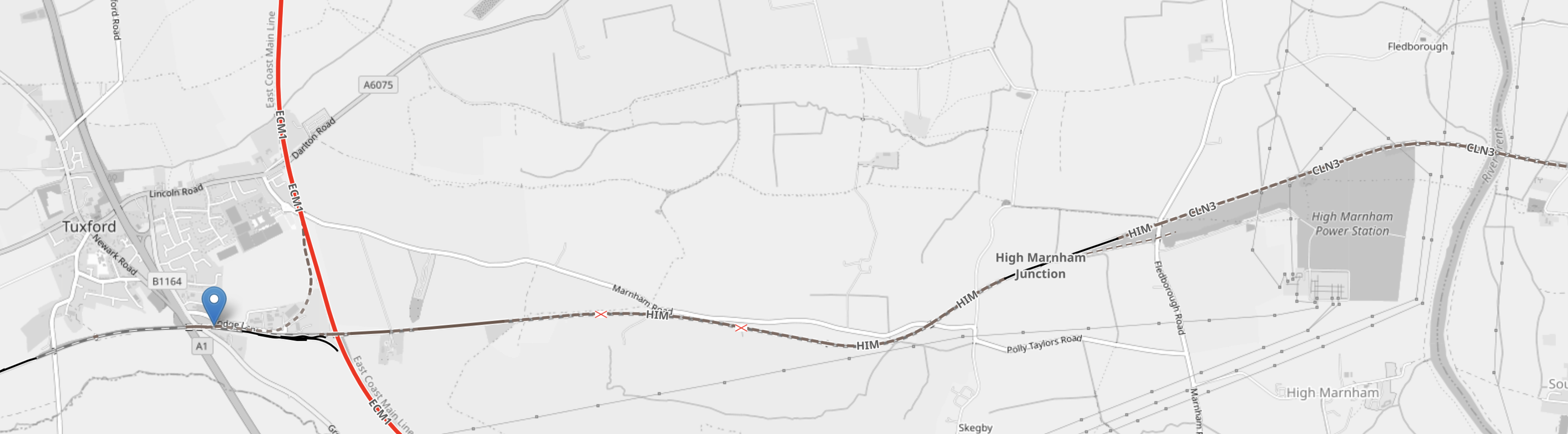
Note.
- The blue arrow is Tuxford West junction.
- The North-South red track is the East Coast Main Line. East-West track indicated by the blue arrow is Network Rail’s Test Track
- The grey area, to the South of the Test Track in the East is the former site of High Marnham power station, where GeoPura have their hydrogen facility.
- If you continue East on the Test Track it connects to the Sheffield and Lincoln Line at Pye Wipe junction.
Sheffield could be the sort of city, that would need a lot of hydrogen to decarbonise.
Has Hydrogen Been Transported From ICI’s Former Site At Runcorn By Rail
I ask this question, as I used to work at Runcorn in the 1960s, and I don’t remember seeing any hydrogen railway wagons.
I asked Google AI, the question in the title of this section and received this answer.
Hydrogen is typically transported from the INEOS (formerly ICI) site in Runcorn via pipeline or by road in cryogenic liquid tanker trucks or gaseous tube trailers, but it has not been historically transported by rail from that specific site.
The first ever trial shipment of hydrogen by rail on Britain’s network took place only very recently, in December 2025, as part of an industry innovation event. This trial involved transporting hydrogen containers from Doncaster to High Marnham, adjacent to the HyMarnham Power green hydrogen production facility.
It looks like my memory and Google AI agree.
CO2 to SAF: A One-Step Solution
The title of this post is the same as that of this article on the Chemical Engineer.
This is the sub-heading,
Oxford spinout OXCCU has launched a demonstration plant at London Oxford Airport to trial its one-step process of turning CO2 into sustainable aviation fuel (SAF). Aniqah Majid visited the plant to investigate the benefits of its “novel” catalyst
One word in this sub-heading caught my eye.
When I was a young engineer in the Computer Techniques section in the Engineering Department at ICI Plastics Division, I did a small mathematical modelling project for this chemical engineer, using the section’s PACE 231-R analogue computer.

He was impressed and gave the 23-year-old self some advice. “You should apply that beast to catalysts.”
I have never had the chance to do any mathematically modelling of catalysts either at ICI Plastics or since, but I have invested small amounts of my own money in companies working with advanced catalysts.
So when OXCCU was picked up by one of my Google Alerts, I investigated.
I like what I found.
The three raw ingredients are.
- Green Hydrogen
- Carbon dioxide perhaps captured from a large gas-fired powerstation like those in the cluster at Keadby.
- OXCCU’s ‘novel’ catalyst, which appears to be an iron-based catalyst containing manganese, potassium, and organic fuel compounds.
I also suspect, that the process needs a fair bit of energy. These processes always seem to, in my experience.
This paragraph outlines how sustainable aviation fuel or (SAF) is created directly.
This catalyst reduces CO2 and H2 into CO and H2 via a reverse water gas shift (RWGS) process, and then subsequently turns it into jet fuel and water via Fischer-Tropsch (FT).
The Wikipedia entry for Fischer-Tropsch process has this first paragraph.
The Fischer–Tropsch process (FT) is a collection of chemical reactions that converts a mixture of carbon monoxide and hydrogen, known as syngas, into liquid hydrocarbons. These reactions occur in the presence of metal catalysts, typically at temperatures of 150–300 °C (302–572 °F) and pressures of one to several tens of atmospheres. The Fischer–Tropsch process is an important reaction in both coal liquefaction and gas to liquids technology for producing liquid hydrocarbons.
Note.
- I wouldn’t be surprised that to obtain the carbon monoxide and hydrogen or syngas for the Fischer-Tropsch process, excess hydrogen is used, so the OXCCU process may need a lot of affordable hydrogen, some of which will be converted to water in the RWGS process.
- The high temperatures and pressures for the Fischer-Tropsch process will need a lot of energy, as I predicted earlier.
But I don’t see why it won’t work with the right catalyst.
The Wikipedia entry for the Fischer-Tropsch process also says this.
Fischer–Tropsch process is discussed as a step of producing carbon-neutral liquid hydrocarbon fuels from CO2 and hydrogen.
Three references are given, but none seem to relate to OXCCU.
OXCCU have a web site, with this title.
Jet Fuel From Waste Carbon
And this mission statement underneath.
OXCCU’s mission is to develop the world’s lowest cost, lowest emission pathways to make SAF from waste carbon, enabling people to continue to fly and use hydrocarbon products but with a reduced climate impact.
It looks like they intend to boldly go.
Conclusion
My 23-year-old self may have been given some good advice.
Huddersfield Station – 30th September 2025
This press release on the Network Rail Media Centre is entitled Huddersfield Station Set To Reopen Next Week With New Temporary Layout.
As it is now next week, I went to have a look at the progress today.
I made a mistake and got on a Grand Central Train, which meant, I had to change at York.
Speeding past Drax power station on the Selby Diversion, I took these pictures.


We were only in a 125 mph diesel, so we couldn’t take advantage of the 160 mph running, that the East Coast Main Line’s new signalling might allow on this section. The Wikipedia entry for the Selby Diversion, says this about the possible speeds.
The line was the first purpose-built section of high-speed railway in the UK having a design speed of 125 mph; however, research by British Rail in the 1990s indicated that the route geometry would permit up to 160 mph operation, subject to the necessary overhead line equipment and signalling upgrades. The new line also avoided the speed restriction over the swing bridge at Selby. The former ECML route, the NER’s 1871 York and Doncaster branch line, was closed from Selby northwards.
As the Selby Diversion opened in 1983, I wouldn’t be surprised that the calculations were performed on British Rail Research’s Pace 231-R, which was similar to the one I used at ICI and the pair, that NASA used calculate how to land Apollo on the moon.
When I eventually got to Huddersfield, I took these pictures.


Note.
- In I’ve Just Glimpsed The Future Of Train Travel Across The North Of England And I Like It, there are pictures of Huddersfield station, that were taken on the 21st August, soon after the work started.
- In Huddersfield Station – 15th December 2023, there are pictures of Huddersfield before the work started.
- Much of the work seems to have been done at the Western end of the station to lengthen the platform on the Penistone Line to Sheffield.
- Platform 2 for the Penistone Line has also been renumbered Platform 1.
Work still to be carried out at Huddersfield station, includes refurbishing the roof, installing the electrification and adding a couple of new platforms.
These are my thoughts.
Which Platforms Will Be Electrified?
This OpenRailwayMap shows the proposed electrification in Huddersfield station.

Note.
- The blue arrow in the North-East corner of the map indicates Huddersfield atation.
- The two red-and-black tracks going diagonally across the map are the Hudderfield Line.
- The red-and-black colour, indicates that the two tracks will be electrified.
- South of these two tracks, the Penistone Line sneaks into Platform 1 at Huddersfield station.
- The Penistone Line goes to Sheffield in a South-Westerly direction.
- There appears to be a crossover, so that trains from the Penistone Line can use both Platforms 1 and 2 in Huddersfield station.
- The OpenRailwayMap appears to show planned electrification between Stalybridge and Leeds stations.
- To the East of Leeds planned electrification is shown as far as Micklefield and Church Fenton stations.
Once installed, this electrification will create a complete electrified route across the Pennines from Liverpool Lime Street in the West to the East Coast Main Line in the East.
This OpenRailwayMap shows the planned electrification between Micklefield and Hull stations.
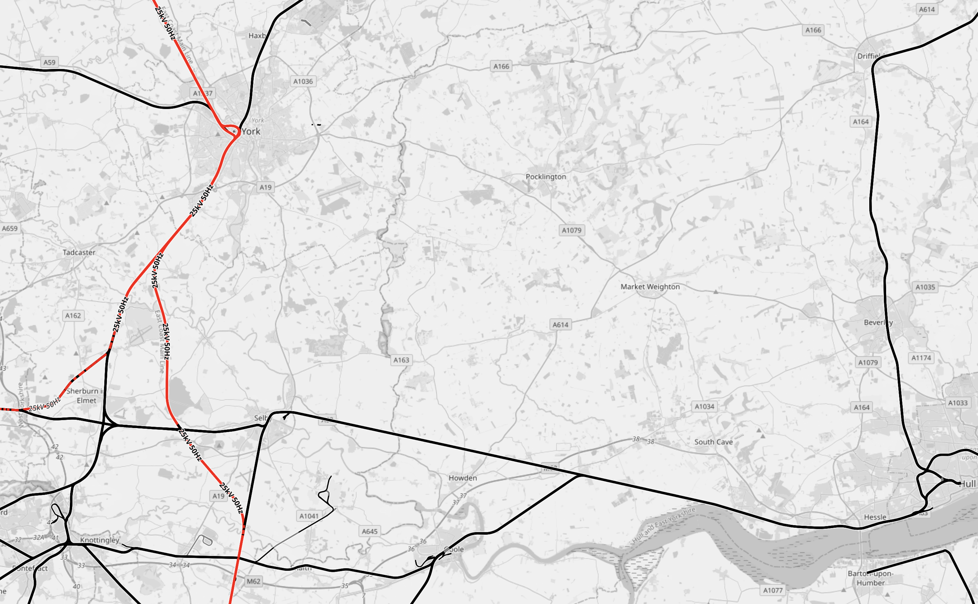
Note.
- Red tracks are electrified.
- Black tracks are not electrified.
- York is in the North-West corner of the map, with the electrified East Coast Main Line going through the station North-South.
- South of York, the East Coast Main Line now splits.
- The Western branch includes an electrified line to Micklefield station, Neville Hill depot and Leeds station.
- The Eastern Branch is the Selby Diversion, which is an electrified 160 mph line, that avoids the Selby coalfield.
- Running West-East across the map is the unlectrified Micklefield and Hull Line, which goes via Selby.
- Hull is in the South-East corner of the map.
- Hull is 42 miles from Micklefield and 36.1 miles from the Temple Hirst junction on the Selby Diversion, so it is within range of battery-electric trains, with charging at Hull station.
- Hitachi’s battery-electric Class 802 trains, used by Hull Trains and TransPennine Express, which are currently on test, should certainly be able to serve Hull.
Hull can become an electrified station, without the expense and disruption of full electrification.
How Long Is Platform 1 At Huddersfield Station?
This OpenRailwayMap shows the new Platform 1 at Huddersfield station.

Note.
The blue arrow indicates Huddersfield station.
- The three darker orange lines indicate the two through platforms 2 and 3, and the reconfigured bay platform 1.
- There is a cross-over between platforms 1 and 2, which connects Platform 2 to the Penistone Line.
- In the South-West corner of the map is a hundred metre scale.
- Using the scale, I estimate that the length of the bay platform 1 is around 120 metres.
- In the last two rows of pictures in the gallery of this post, a three car Class 150 train is shown in Platform 1.
- A three car Class 150 train is approximately sixty metres long.
Looking at the pictures, I wouldn’t be surprised if the new platform has been designed to take two three-car Class 150 trains. It would certainly take a pair of two-car Class 150 trains.
Other trains and their lengths that might use the platform include.
- Class 170 – three-car – 70.85 metres
- Class 195 – two-car – 48.05 metres
- Class 195 – three-car – 71.40 metres
- Class 195 – 2 x two-car – 96.10 metres
- Class 810 – five-car – 120 metres
The Class 810 uses 24 metre cars, so that a pair of trains, will fit in St. Pancras. But with perhaps selective door opening could a single Class 810 train run a St. Pancras and Huddersfield service, perhaps with a split and join at Sheffield.
Electrification Across The Pennines
The TransPennine Route will be electrified between Liverpool Lime Street and Micklefield stations, once the current works between Huddersfield and Leeds are complete.
Sections without electrification include.
- Bradford Interchange and Doncaster – 52.1 miles
- Cleethorpes and Doncaster – 52.1 miles
- Harrogate and Leeds – 18.3 miles
- Hazel Grove and Doncaster – 52.6 miles
- Hull and Micklefield – 42 miles
- Hull and Temple Hirst junction – 36.1 miles
- Saltburn and Northallerton – 28.1 miles
- Sunderland and Northallerton – 46.8 miles
- Scarborough and York – 42.1 miles
I expect that Hitachi trains with batteries or CAF’s tri-mode trains will be able to handle these routes in a low-carbon manner.
Electrification Between Stalybridge And Huddersfield
This section is shown as being electrified on OpenRailwayMap.
But as it is only 18 miles and includes the Standedge Tunnels will the route use battery-electric trains?
Visiting The Consultation For Ferrybridge Next Generation Power Station At Knottingley
Yesterday, I visited the first meeting for the consultation on Ferrybridge Next Generation Power Station, which was held in the old town hall at Knottingley.
This Google Map shows the power station in relation to Knottingley.
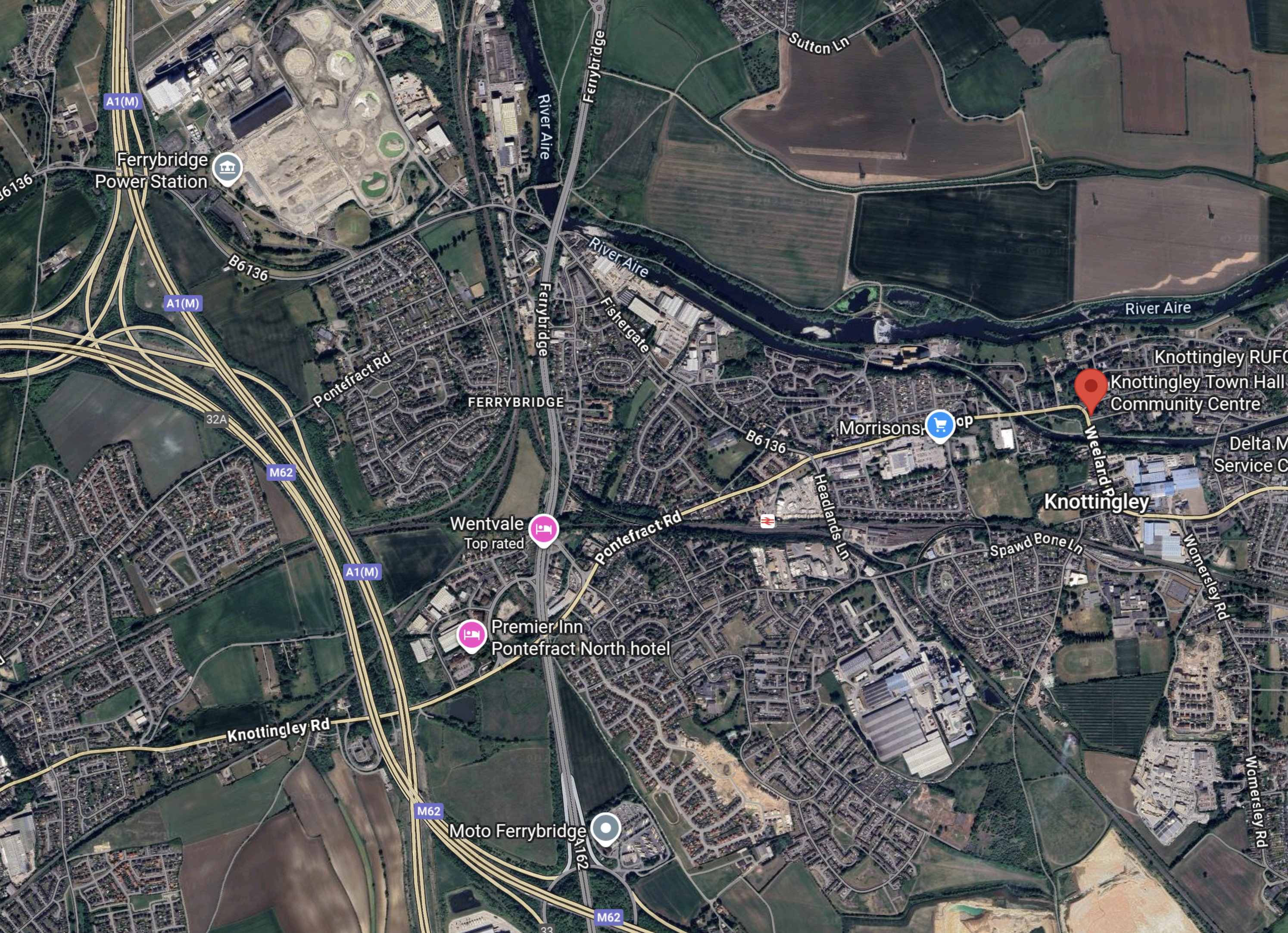
Note.
- The meeting was held in the Knottingley Town Tall Community Centre, which is marked by the red arrow.
- I had arrived by train from Wakefield at Knottingley station and I was lucky enough to be able to get a taxi to the Town Hall.
- Knottingley station is marked on the map about a twenty-minute walk to the West of the Town Hall.
- The Ferrybridge power station site is in the North-West corner of the map and appears to be bordered by the B6136 road.
- The A1 (M) and the M 62 motorways run North-South past the power station site.
- The A (M) motorway continues North-South to Newcastle and Scotland, and London respectively.
- The M62 motorway continues West-East to Liverpool and Manchester, and Hull respectively.
- The well-appointed Moto Ferrybridge services is accessible from both motorways.
This OpenRailwayMap shows the rail lines in the area.

Note.
- The A 62 and A 1(M) motorways running down the West side of the map.
- Knottingley station is on the Pontefract Line, and is marked by a blue arrow.
- The Pontefract Line could have connections from both East and West to the Ferrybridge power station site via Ferrybridge Power Station junction.
- The loop, where the merry-go-round coal trains turned, appears to be still intact at the North of the power station site.
Will these rail lines be any use in the building and operation of the new power station?
These are my thoughts.
Fuel For The Power Station
The brochure for the consultation says this about the fuel for the Ferrybridge Next Generation Power Station.
Ferrybridge Next Generation Power Station will be designed to run on 100% hydrogen, natural gas or a
blend of natural gas and hydrogen.
The brochure has an informative section, which is entitled Natural Gas Pipeline Corridors.
Additionally, I should say, that I lived within a couple of hundred metres of a major gas pipeline in Suffolk, for over twenty years and it was the most unobtrusive of neighbours.
The brochure also says this about hydrogen safety.
As with all of our sites, appropriate measures will be
in place to ensure safe operation. Hydrogen is not
inherently more dangerous than other fuel sources.Hydrogen is flammable and must be handled with care,
just like other flammable fuels. To ignite, hydrogen
must be combined with an additional oxidising agent,
such as air or pure oxygen, in a specific concentration
and with an ignition source (a spark).
It is nearly sixty years ago now, since I worked as an Instrument Engineer, in ICI’s Castner-Kellner works at Runcorn, where hydrogen, chlorine and caustic soda were produced by the electrolysis of brine.
The plant was an unhealthy one, as it used a lot of mercury and my main task, was to design instruments to detect mercury in air and operators’ urine.
The Wikipedia entry for the Castner-Kellner process is a fascinating read and explains why it is being replaced by much better modern mercury-free processes.
I asked Google AI, if the Castner-Kellner process is still used and received this reply.
No, the Castner-Kellner process, a type of mercury cell for producing chlorine and caustic soda, is now largely obsolete due to occupational health and mercury pollution concerns, though a few plants may still operate globally. Modern chlor-alkali processes primarily use safer diaphragm cell and membrane cell technologies to produce chlorine and other chemicals from brine electrolysis.
I suspect that countries, where life is cheap, still use this process, which is very dangerous to those that work on the plant.
INEOS now own ICI in Cheshire and they still produce a large proportion of the hydrogen, chlorine and caustic soda, that the UK needs, but in a much safer way.
The question has to be asked about how hydrogen will be delivered to the Ferrybridge site.
Consider.
- SSE are developing a large hydrogen store at Aldbrough.
- Centrica are developing a large hydrogen store at Brough.
- Both of these stores could be connected to the German AquaVentus system, as the Germans are short of hydrogen storage.
- There is an East Coast Hydrogen Delivery Plan, which could probably have an extension pipeline to the Ferrybridge site.
- The East Coast Hydrogen Delivery Plan, talks of a hydrogen capacity of 4.4 GW.
I don’t feel, that this is the sort of project, that will be delivered until the mid-2030s, at the earliest.
There is also one other important development, that will require hydrogen at Ferrybridge.
I asked Google AI, if there will be hydrogen-powered coaches by 2030 and received this reply.
Yes, there will be hydrogen-powered coaches and buses by 2030, particularly in the UK and EU, with government strategies and funding promoting their deployment, especially for routes requiring high range and quick refueling where battery-electric models may be less suitable. For example, the EU’s CoacHyfied project is developing fuel cell coaches, and the UK government envisions hydrogen playing a role in its transport decarbonization by 2030, with potential to accelerate its zero-emission bus goals.
The nearest you can get to a hydrogen-powered coach in England, is to take an upmarket Wrightbus upmarket hydrogen-powered bus between Sutton station and Gatwick Airport.
- It is mouse quiet and vibration-free.
- It handles the hills with alacrity.
- I wrote about my journey in Sutton Station To Gatwick Airport By Hydrogen-Powered Bus.
That journey convinced me of the superiority in many ways of a hydrogen bus or coach over its diesel cousins.
I believe that this superiority will see large growth in hydrogen-powered long-distance coaches in the next few years.
But I also feel that some specialist transport, like horse transport, will go the hydrogen route.
As there are services at Ferrybridge, where two important motorways cross, I can envisage that the services will need to be able to refuel passing hydrogen buses, coaches trucks and other heavy vehicles, as well as the occasional car.
So would it be possible to supply hydrogen for the motorway services, by the same route as the power station?
I believe that the hydrogen could come from Saltend to the East of Hull, so I gave Google AI the phrase “Saltend zero-carbon hydrogen” and received this reply.
Saltend is home to several initiatives for producing and utilizing zero-carbon hydrogen, most notably the H2H Saltend project by Equinor, which aims to build the world’s largest hydrogen production plant with carbon capture capabilities by 2026 to supply industrial users at the Saltend Chemicals Park. Additionally, a new green hydrogen facility is planned for the park by Meld Energy with a target operation in early 2027, and a separate low-carbon hydrogen plant by ABP, HiiROC, and px Group is also being developed to meet local industrial demand. These projects collectively contribute to the broader Zero Carbon Humber initiative, which seeks to significantly reduce industrial emissions in the region.
Note.
- Saltend will certainly have enough zero-carbon hydrogen for everybody who wants it.
- Delivery dates in a couple of years are being talked about.
- Local industrial demand could be satisfield using specialised trucks, just as ICI used in the 1960s.
- As the Germans want to connect their AquaVentus system to Humberside, any excess hydrogen, could always be sold across the North Sea.
- OpenRailwayMap shows that Saltend is rail-connected.
But how do you get hydrogen between Saltend and Ferrybridge?
I am sure, that hydrogen could be delivered by truck from Saltend to Ferrybridge, but would the locals allow a stream of hydrogen trucks on the roads.
On the other hand, both Saltend and Ferrybridge are both rail-connected, so would it be possible to deliver the hydrogen by rail?
Google AI says this about railway wagons for hydrogen.
Railway wagons for hydrogen transport include liquid hydrogen tank cars (tankers) for transporting cryogenic liquid hydrogen and compressed gas tank cars for carrying hydrogen in its gaseous state or bound within carrier mediums like ammonia or methanol. Hydrogen fuel cell technology is also being developed for use on trains themselves, with a hydrogen fuel cell generator wagon providing power for main-line, non-electrified freight routes.
I believe that it will be possible to develop trains of an appropriate length to shuttle hydrogen between where it is produced and where it is used.
Such a specially-designed shuttle train would be ideal for moving hydrogen between Saltend and Ferrybridge.
- Once at Ferrybridge, the train would be connected to the local hydrogen system feeding the power station, the motorway services and any local businesses that needed hydrogen.
- The trains could be hydrogen fuel cell powered, so they could use any convenient route.
- Like hydrogen powered buses, I suspect they could be mouse quiet.
- The trains would be sized to perhaps deliver a day’s hydrogen at a time.
- There could only be minor changes needed to the rail system.
- If required, the trains could could deliver their cargo in the dead of night.
It could even be based on the contept of the TruckTrain, which I wrote about in The TruckTrain.
The British Mini Nuclear Fusion Reactor That Actually Works
The title of this post, is the same as that as this article in The Times.
This is the sub-heading.
The only functional model in the world is so small it fits on a table and is set to help diagnose and cure cancer
These are the first two paragraphs, which add more details.
There are a few things that mark this nuclear fusion reactor out as unusual. For one, it is rather small: it could fit on a table top. For another, this research model currently has a little more gaffer tape than you might expect of the energy technology of the future.
But the biggest difference between it and its competitors is that this nuclear fusion reactor, in a warehouse north of Bristol, is actually working. And it is on the cusp of doing something more unusual still: making money.
It almost makes you think, that it should be filed under Too Good To Be True!
In the late 1960s, I shared an office at ICI Mond Division in Runcorn, with a guy, who was working on a process to make acetylene by a revolutionary route.
The process never worked, but now it has turned up being used by a company called HiiROC to make hydrogen.
They are also backed by some big names like Centrica, Hyundai, Kia and others.
I wonder how many other old ideas are finally ripe for developing, due to improvements in manufacturing and systems to control them.
Can You Measure Blood Pressure At The Ankle?
Consider.
- As long, as I can remember my left foot has always been larger than my right.
- Over the last few years increasingly, my left foot has often been a stronger shade of red, than my right.
- I also know, that after my stroke a specialist physiotherapist found that my left leg was stronger than my right.
I also know that I have a strange leaky skin.
- I had my stroke in 2010 in Hong Kong and was looked after in a private Chinese hospital.
- They were very strict and measured all the bodily fluids, that I passed.
- They didn’t collect any urine, so they accused me of throwing all my water away.
- I was not guilty, as I was drinking it all.
So they fitted me with a catheter and guess what? They still didn’t collect anything.
It was evidence that my skin is not good at holding water.
So why do I want to measure the blood pressure at my ankle? Or in fact both ankles.
In my ICI days in the 1960s and 1970s, I was helping chemical engineers to understand chemical plants and reactions, by looking at flows and pressures in the various pipes of the plant or experimental rig.
But I do wonder, if the red nature of my left foot, is due to some sort of irregularity in the blood flow to my left leg.
